Methods and systems for multiplexing ir-mediated heating on a microchip

a microchip and multiplexing technology, applied in the field of methods and systems for multiplexing ir-mediated heating on a microchip, can solve the problems of difficult to maintain homogenous sample temperature, provide amplification times that are not as rapid, and achieve the effect of accelerating the speed of each cycl

Inactive Publication Date: 2005-12-29
UNIV OF VIRGINIA ALUMNI PATENTS FOUND
View PDF14 Cites 45 Cited by
  • Summary
  • Abstract
  • Description
  • Claims
  • Application Information

AI Technical Summary

Benefits of technology

[0025] Using a spinning microchip fabricated from glass, silicon, ceramic or plastic, infrared (IR)-mediated temperature cycling of small volumes of solution is possible in multiple chambers on the same device. The present invention approach, which allows for IR heat to be delivered from several low-power IR sources to many microareas (microchannels, microchambers, etc.) on a circular microchip, affords a method and system for multiplexed thermocycling, such as that for PCR-amplification of DNA, on a single microchip device. The IR sources are positioned relative to the microchip in a manner that allows maximum, efficient and equivalent exposure of the IR radiation to the micro-heating areas. By spinning the circular microchip at the appropriate sp

Problems solved by technology

The limitations associated with conventional thermocyclers in the past, primarily that rate at which the temperature can be changed, provides amplification times that are not as rapid as they could be.
Accordingly, thermocycling of samples can become a time consuming process.
In addition, these methods often require the precise control of temperature at each stage of the cycle; exceeding a desired temperature can lead to inaccurate results.
Typicall

Method used


Image

  • Methods and systems for multiplexing ir-mediated heating on a microchip
  • Methods and systems for multiplexing ir-mediated heating on a microchip
  • Methods and systems for multiplexing ir-mediated heating on a microchip

Examples


first embodiment

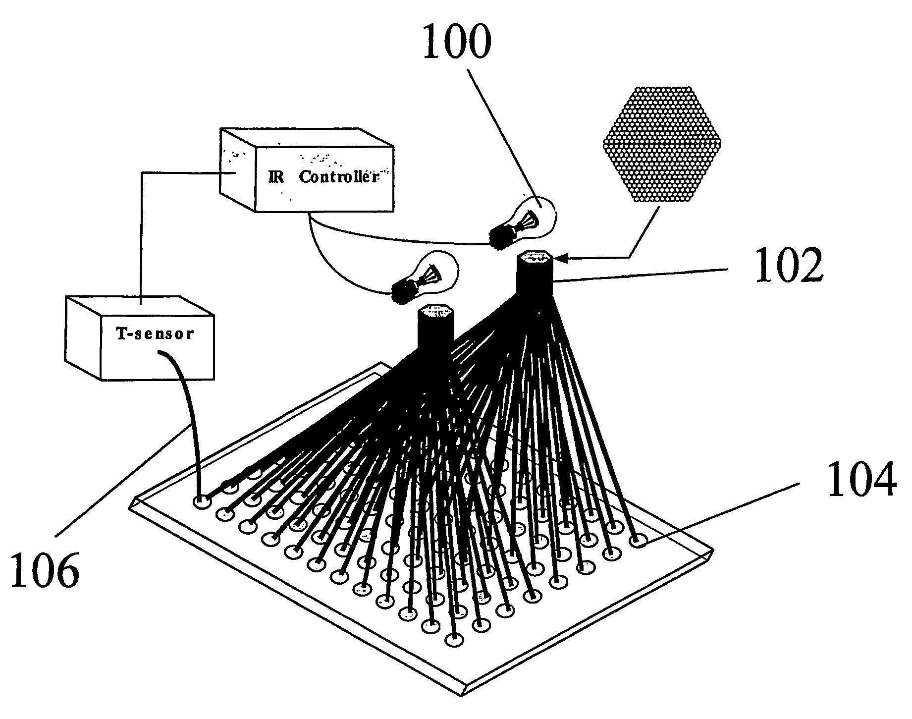
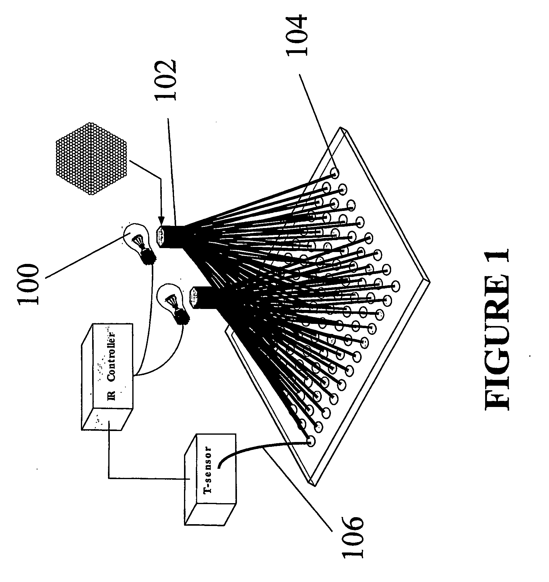
[0059] A first embodiment involves using a fiber optic bundle to deliver heating radiation to the micro-heating areas. The irradiation from a powerful IR source can be focused into a bundle of optical fibers having the appropriate character for propagating the IR from the source to the micro-heating area In order for that to be a functional approach: 1) the IR source would have to have enough power to provide the appropriate amount of power to each micro-heating area; 2) there would have to be equivalent power distribution to each chamber; 3) each fiber would have to have equivalent radiation transmission properties and minimal power loss over the length of the fiber; and 4) there would have to be cooling homogeneity over the entire surface of the chip. Optical fibers produced for the telecommunications industry should be ideal for this purpose since they are designed for light propagation in the 1.3-1.4 μm range, exactly the preferred part of the spectrum used in IR-mediated heatin...

second embodiment

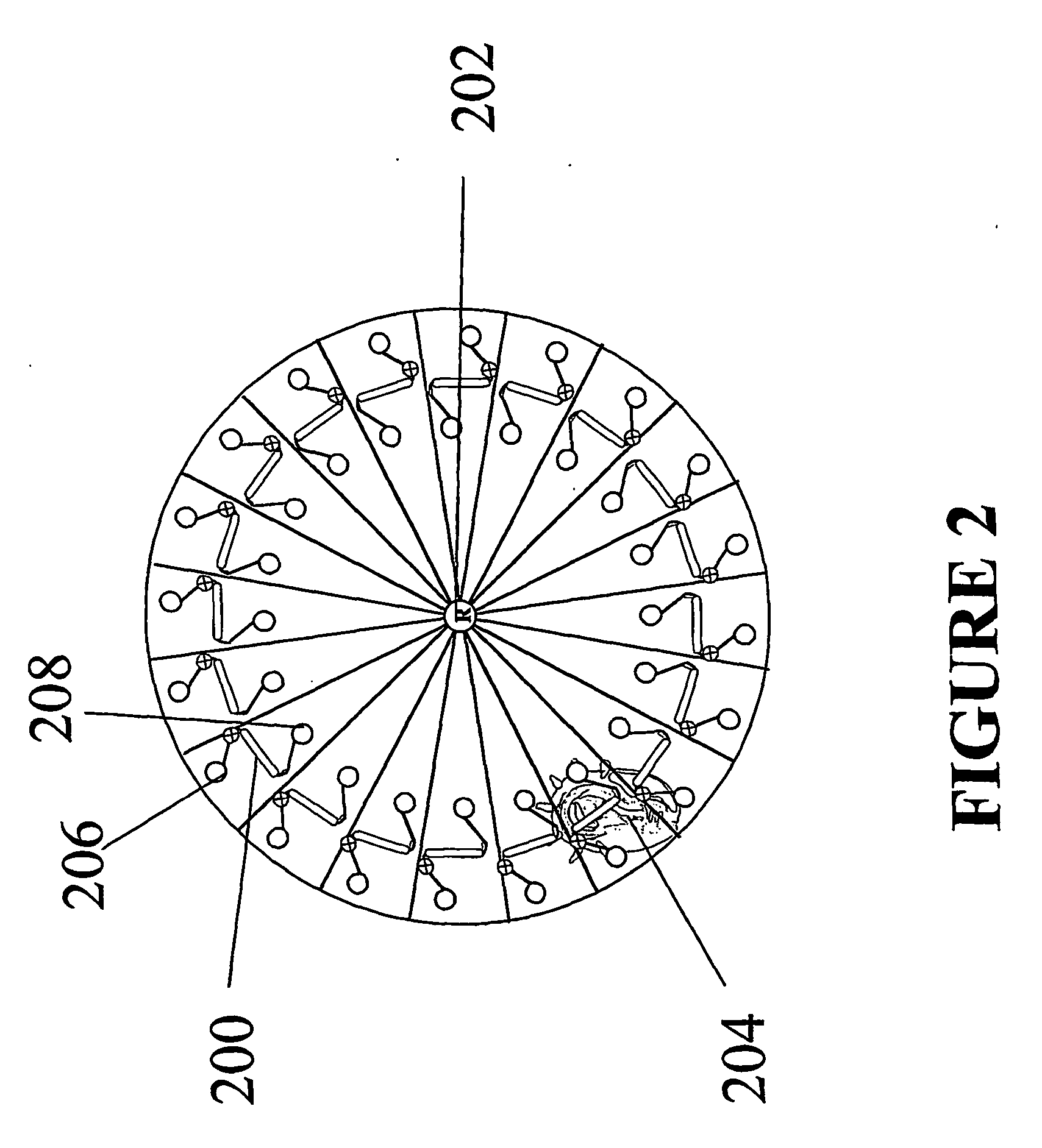
[0062] A second embodiment involves a spinning microchip having a thermocycling chamber / reservoirs design. In this approach, all IR sources are impingent on all micro-heating areas. That can be accommodated by using a circular microchip depicted in FIG. 2, where the thermocycling chambers 200 are arranged in a circular configuration on the chip. With that approach, all of the micro-heating areas fall on a concentric ring equidistant from the rotor 202, so that a spinning about the rotor would allow for all micro-heating areas to be accessed from a single static point. That creates the opportunity for an IR source(s) 204 to irradiate all micro-heating areas while the chip spins, thus avoiding inconsistencies with power impingent on any particular micro-heating area In addition, remote temperature sensing (not shown in FIG. 2, shown as element 400 in FIG. 4) would allow for more than a single micro-heating area to be interrogated for solution temperature.

[0063] With a microchip contai...

third embodiment

[0066] A third embodiment involves an IR bank and optical fibers to deliver IR radiation to micro-heating areas. This embodiment marries the concept of the first two embodiments into a single concept. With this configuration, there is a bank or array of IR sources 502 remote from the chip and, using optical fibers 504, the IR light is brought to the micro-heating areas 506 without over crowding the space above or below the chip.

[0067] Spinning the microchip 500 at a speed that allows for delivery of the appropriate amount of power to each micro-heating area 506 should allow for the desired temperature acquisition. In addition, a remote temperature probe (not shown) position above the micro-heating area 506 of the spinning chip 500 allows for temperature interrogation of all of the micro-heating areas, provided the time constant for sensing is small enough.


PUM


Abstract

The present invention relates to methods and systems for rapid multiplexed heating of a plurality of small volume samples on a microchip. More specifically, the present invention relates to methods and systems for non-contact temperature cycling of the samples using infrared (IR)-mediated heating of small, micro to nanoliter, volume samples, wherein each cycle can be completed in as little as a few seconds. Depending on the system used, the present invention involves a spinning microchip or an immobile microchip having a plurality of micro-heating areas thereon. In the case of the spinning chip, the micro-heating areas are located in a circular configuration on the chip, so the micro-heating areas can be accessed by static heating source(s) by spinning the microchip. In case of the immobile microchip, fiber optics are used to direct radiation from a heating source or multiple heating sources directly to the micro-heating areas on a microchip.

Description

FIELD OF THE INVENTION [0001] The present invention relates to methods and systems for rapid multiplexed heating of a plurality of small volume samples on a microchip. More specifically, the present invention relates to methods and systems for non-contact temperature cycling of the samples using infrared (IR)-mediated heating of small, micro to nanoliter, volume samples, wherein each cycle can be completed in as little as a few seconds. BACKGROUND OF THE INVENTION [0002] There is an on-going need to miniaturize and multiplex thermocycling, especially for the polymerase chain reaction (PCR) amplification, process into a platform that is fast, convenient and inexpensive. Microtiter plate formats have been the main contributors to high throughput PCR but still utilize conventional block heater, or forced air thermocyclers. While the number of samples that can be cycled simultaneously (96, 384 or 1536) is impressive, amplification speed is not. The limitations associated with convention...

Claims


Application Information

Patent Timeline
IPC IPC(8): B01L3/00B01L7/00C12M1/34G01N35/00
CPCB01L3/5027B01L7/52B01L7/54B01L2200/147B01L2300/0803G01N2035/00415B01L2300/1838B01L2300/1844B01L2300/1872B01L2400/0409B01L2300/0829
Inventor LANDERS, JAMES
Owner UNIV OF VIRGINIA ALUMNI PATENTS FOUND
Why Eureka
Try Eureka