Particle separation

a technology of particle separation and separation efficiency, applied in the direction of lorentz force separation, open gradient mangetic separator, water/sludge/sewage treatment, etc., can solve the problems of high cost, high pressure, and limited amount of usable water in the world, so as to improve the speed and separation effectiveness, reduce the cost, and weaken the molecular bond of the targeted material

Inactive Publication Date: 2006-01-26
SHORTS GRAEME STEWART
View PDF2 Cites 39 Cited by
  • Summary
  • Abstract
  • Description
  • Claims
  • Application Information

AI Technical Summary

Benefits of technology

[0089] The field effect once applied does leave a charge that has an ongoing effect for a limited period of time, which is subject to flow and pulse rate. The ratio of the charge to flow rate can vary as much as 100:1. If properly applied energy can be saved and the device can be considerably cost effective.
[0090] After being subjected to the applied pulsed field given by the primary inductor around the energiser tube, the targeted in-flow material is in a confused but free state. The targeted material can then be subjected to a secondary inductor further down the flow path of the energiser tube to improve the speed and separation effectiveness. This inductor applies a positive charge to the targeted material in flow, which prepares it for the separation that takes place within the hydrocyclone or laminar flow separator. The hydrocyclone is equipped with two separate coils at the top and bottom of the device that provide magnetic fields. The coil positioned at the top of the cyclone is a tuning device that is similar to the primary inductor around the energiser tube. Its purpose is to further weaken the molecular bond of the targeted materials. The coil at the lower end of the cyclone applies a negative or rejection charge. The purpose of this is to attract the positively charged targeted materials to the narrow portion of the cyclone and out the underflow end. The combination of centrifugal forces inside the cyclone and the attraction of the particles to the lower portion of the cyclone are the basis for the separation. The magnetic field created by the inductor will attract positively charged particles for exit out of the underflow end and reject negatively charged particles for exit out of the overflow end of the cyclone. The negatively and positively charged particles are not the normal negative and positively charged particles found in saline water but particles that are separated and are not separated due to their atomic resonate frequency. This is the same principle that applied to an Inductively Coupled Plasma analyser known as ICP analysis. The ICP analysis depends on separating the natural resonant frequencies of compounds to be analysed and reads the resulting frequencies and strength allowing analysis to parts per billion. Using this same principle the resonate frequencies are applied instead of generated causing the separation of the desired ions.

Problems solved by technology

It requires the use of high pressures which inevitably involves high costs.
This is because the separation of two liquids is much more difficult than other separations due to relatively low-density differences between fluids as compared to the separation of solids or gasses, which have relatively high-density differences.
The amount of usable water in the world is limited.
This is because most of the water that covers the world is too salty or too contaminated for use.
However, with population increases and industry and agricultural demands, freshwater resources are quickly becoming scarce.
Therefore, water scarcity is quickly becoming a global concern as more countries' freshwater sources are becoming depleted.
According to the World Water Council, more than one billion people lack access to clean drinking water and some two and a half billion do not have adequate sanitation services.
Solutions such as water conservation programs and devices and new reservoirs have been developed but these solutions are only short-term solutions.
Conservation techniques and water storage are both limited by current water resources.
Conservation cannot solve a problem such as a freshwater resource becoming dry or too contaminated.
Water shortages may be the result of events such as droughts, contamination, salt-water intrusion, or limited water sources, even after conservation methods have been implemented.
Distillation works well but requires large quantities of heat energy, and costs have been prohibitive for nearly all but the wealthiest nations, such as Kuwait and Saudi Arabia.
However, the permeable membranes have relatively short life spans and are highly susceptible to contaminants in the source water, particularly chlorine and fine silt.
The membranes tend to become “fouled” or “scaled” over time by organic and inorganic substances present in the water.
Although new and improved membranes such as the thin composite membrane are being introduced to help solve such problems, APS will not have equipment that introduces these types of problems to the desalination system.
Another problem with Reverse Osmosis that APS will improve upon is the process's use in places like the Middle East and the Gulf of Mexico.
Gulf water has more salt than ocean water, therefore making desalination more difficult to complete.
In addition, the warm Gulf water reduces the useful life of the membranes.
Certain characteristics about desalination make it an extremely costly technology.
Capital investment and operations are expensive for all desalting options because pipes and equipment require corrosion-resistant materials, while special pre-treatment filters and cleaning membranes require frequent backwashing to remove the rapid accumulation of silt.
Organic fouling is also a problem if the seawater is not disinfected and is directly pumped into the plant.
However, cost effective methods of disinfection usually damage the membranes and the excess disinfectant must be removed prior to the Reverse osmosis membranes.
Thus, due to its simple construction, the installed cost of the APS unit will often be significantly less than the equivalent reverse osmosis unit.
This discharge of unusable brine can have a damaging environmental effect directly impacting things such as marine wildlife, plants and water quality.
However, as technology improves, the cost of desalination is going down but it is still too high for most agricultural uses to make economic sense.
The high price of agricultural water requires governments to subsidise the process.
Subsidisation is done to provide water, food or jobs but it also has negative consequences.
Therefore, water conservation technologies do not spread and too few investment funds and revenues are available to maintain water infrastructure, research, and training systems.

Method used


Image

  • Particle separation
  • Particle separation
  • Particle separation

Examples


Embodiment Construction

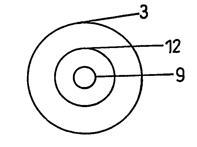
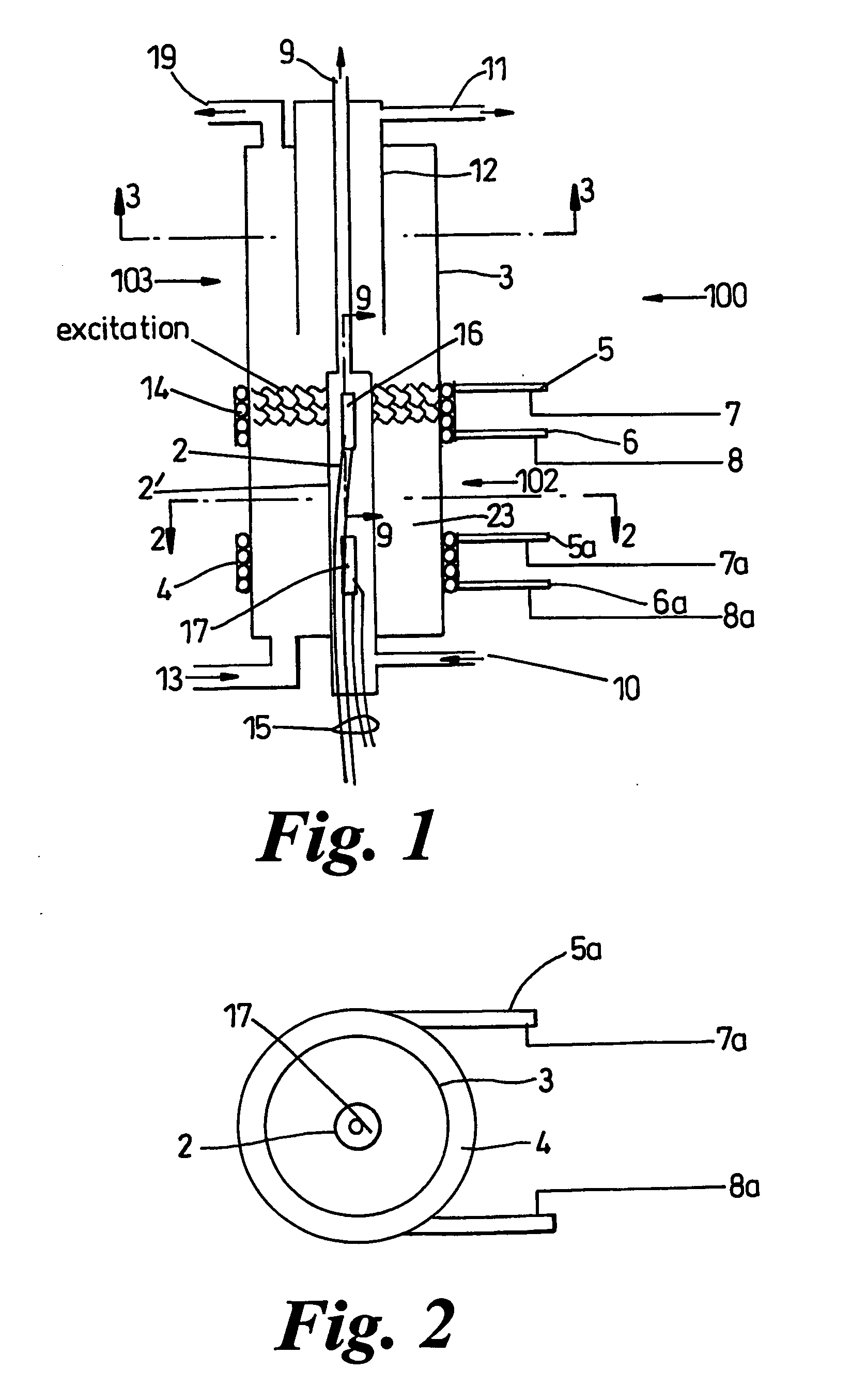
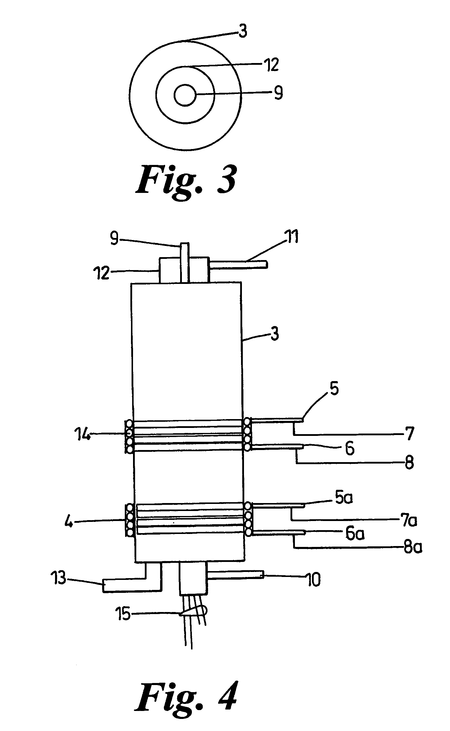
[0110] The invention contemplates a laminar particle separator for liquid-liquid separation, and this will be described with reference to FIGS. 1 to 4. The lower section (102) of the laminar particle separator (100) is made of a non-metallic housing (3) with an annulus (23) defined between the wall (2′) of a chamber (2) and housing (3). Optionally at least one anode (16) is located in chamber (2) and is cooled with a coolant that circulates around the anode from a first coolant inlet (10) to a coolant outlet (9) leading from the chamber (2).

[0111] The laminar particle separator can use a DC or pulsed DC power source (15), which is preferably pulsating. If the anode (16) is used, the power source (15) is connected to the magnetic coil (14) disposed in the chamber, the magnetic coil (14) being cooled with a second coolant supply. In FIG. 1, a second magnetic coil (4) is also shown wrapped around the housing (3).

[0112]FIG. 1 shows the second coolant streams inlet (5) and outlet (6) o...


PUM

PropertyMeasurementUnit
magnetic fieldsaaaaaaaaaa
pressuresaaaaaaaaaa

Abstract

A laminar or cyclonic particle separator for gas, liquid-liquid and fluidizable solids separation comprised of a section with a non-metallic housing having an annulus and a chamber, an optional anode cooled with a first coolant in and a first coolant out disposed in the chamber, a DC or pulsating DC power source connected to the anode, at least one magnetic coil disposed adjacent the chamber and cooled with a second coolant, a high voltage pulsating DC power source connected to the magnetic coil, and a fluid (gas, liquid or fluidizable solids) inlet port connected to the housing, and also a section with a non-metallic separator tube connected to the housing and disposed within the housing, a first fluid outlet connected to the annulus through the housing. This device can then separate a stream rich in a targeted element (first fluid) and a stream lean in a targeted element (second fluid) from the device and thus discharge a stream almost free of the targeted element or almost 100% the targeted element.

Description

FIELD OF THE INVENTION [0001] The present invention relates to methods and apparatuses for separating gases, liquids or fluidizable solids or separating multiple or discrete ions, compounds, or elements from gases, liquids or fluidizable solids by generating magnetic fields. [0002] The term ‘fluid’ will be used herein to include, where the context admits, liquids, gases and fluidised solids. [0003] The invention also relates to magnetic field devices as applied through magnetic resonance imaging (MRI) and other imaging applications, such as nuclear magnetic resonance imaging (NMRI). [0004] The magnetic fields desirably have highly uniform field strengths and directions (dipole fields), uniform radial gradients of the field strengths within the body of the device (quadrupole fields), or sextupole, octupole, and above fields within the body of the device that are generally uniform. [0005] Uniform and higher order electric field gradients have application in the separation of component...

Claims


Application Information

Patent Timeline
Patent Type & Authority Applications(United States)
IPC IPC(8): B03B13/00B01D17/06B01D45/12G01N24/00B01J19/08B03C1/00B03C1/023B03C1/035C02F1/00C02F1/38C02F1/46C02F1/48
CPCB01D45/12C02F2301/026B03C1/035B03C1/32B03C3/15B03C2201/02C02F1/38C02F1/4604C02F1/48C02F2101/20C02F2103/08C02F2103/10C02F2201/46175C02F2201/483C02F2301/022B03C1/023
Inventor SHORTS, GRAEME STEWART
Owner SHORTS GRAEME STEWART
Why Eureka
Try Eureka