[0018] According to the previous technique developed by the inventors of the present application and disclosed in a co-pending US application, the
image resolution is improved by increasing an effective
voltage of a
charged particle beam column, namely, a
voltage defined by the voltages on the
anode and the sample (absolute value of a difference between the sample and
anode voltages), while maintaining actual
anode voltage so as to, on the one hand, meet a requirement for an accelerating voltage in the column and, on the other hand, prevent breakdown in the system operation. This is implemented by appropriately distributing the voltage supply between the electrodes of the column, namely, anode-
electrode, the cap-electrode, and the sample under inspection, while supplying a certain
negative voltage to the sample. The voltage
supply distribution is adjusted in accordance with the desired accelerating voltage for primary and secondary beams, the desired primary
beam energy landing; and a required operational mode of the column, namely,
normal mode or tilt mode, HAR or non-HAR mode. For non-HAR mode, voltage supplied to the cap-electrode is either slightly lower or substantially equal to that of the sample. For HAR mode, voltage supplied to the cap-electrode is significantly higher as compared to that of the sample.
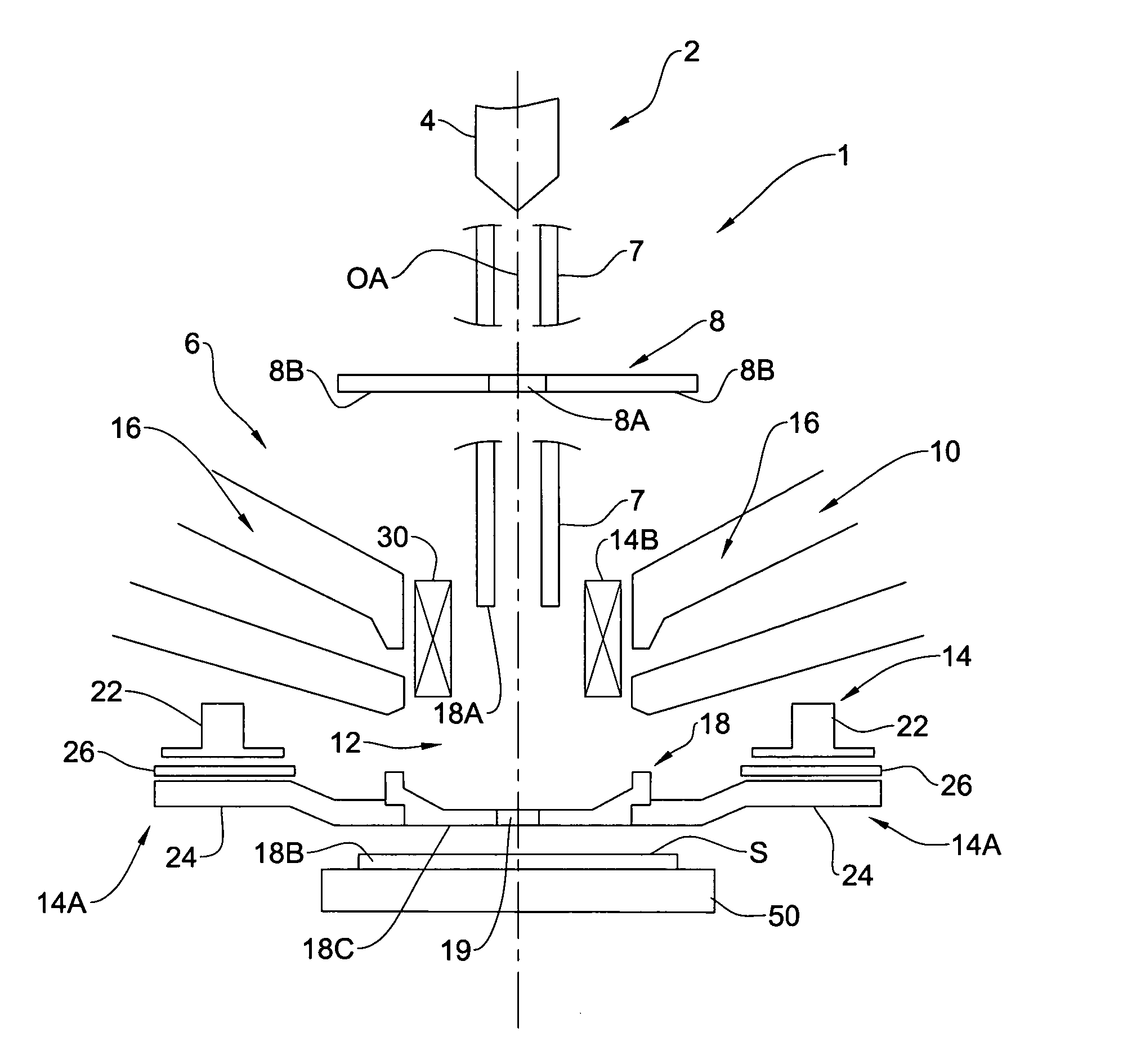
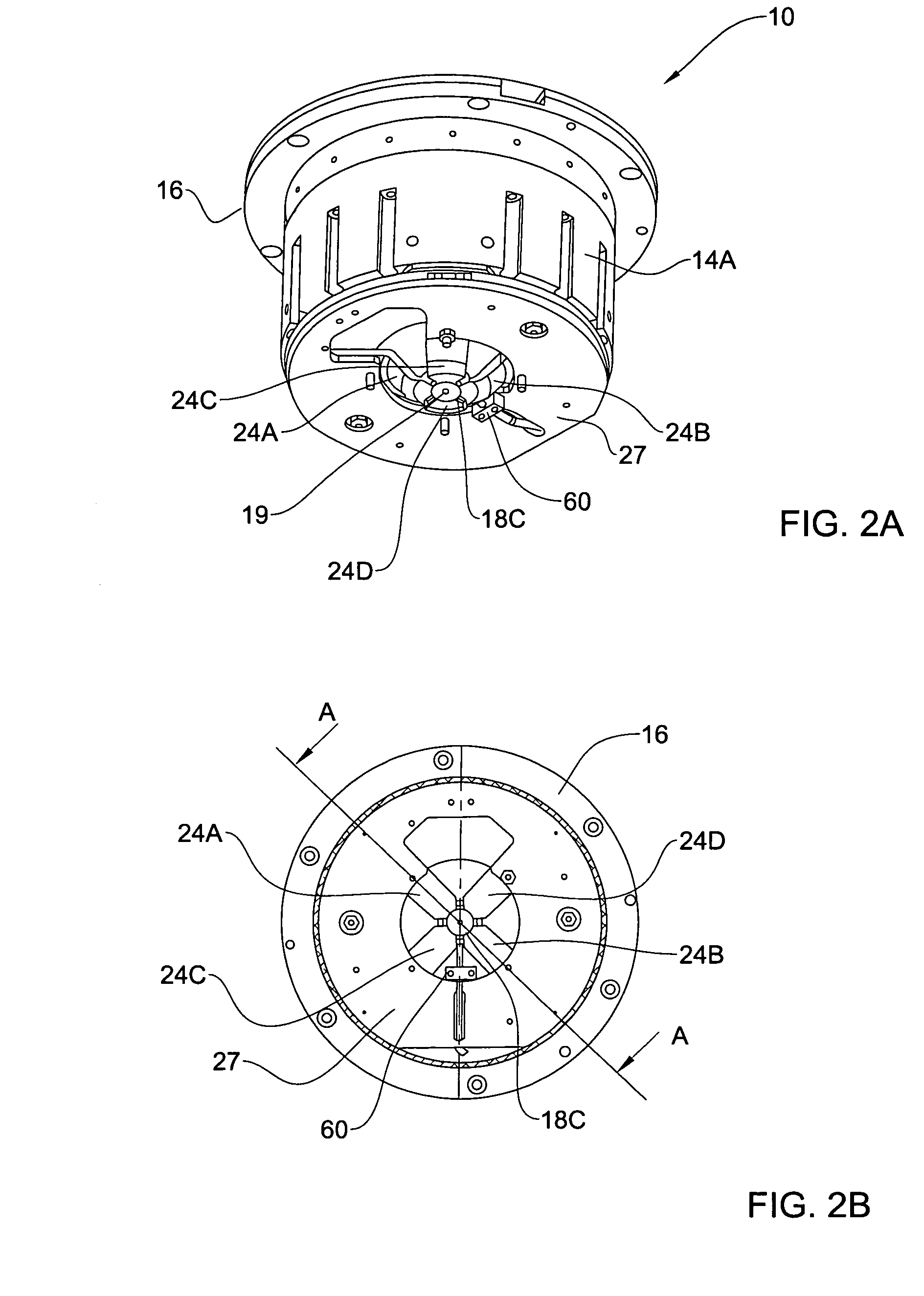
[0021] The above configuration (electrical communication between the polepieces of the magnetic deflector and the cap-electrode and electrical insulation between the polepieces and the other part of the deflector's
magnetic circuit) provides for operating with an increased effective voltage of the column, thus significantly reducing aberrations and improving the efficiency of detection and the
image resolution, even for a low energy primary beam, i.e.,
beam energy of 500 eV and lower, for both normal incidence beam mode and large
electron tilt mode, and for both HAR mode and “non-HAR” mode. The inventors have shown a 10-15% improvement of image resolution when operating with a primary beam energy landing of 500 eV. Additionally, using a very small gap or preferably absence of a gap between the cap and the polepieces provides for reducing the inner
diameter of the polepieces, enabling beam deflection with decreased
electric current through the coils of the magnetic deflector, and increasing the sensitivity of the deflector, i.e., increasing the beam deflection at a given
electric current through the coils of the magnetic deflector.
[0023] According to another aspect of the invention, there is provided a beam directing system for directing a
charged particle beam towards and away from a sample, the system comprising: a lens arrangement having an electrode formed with a beam opening for a
charged particle beam passage therethrough; and a magnetic deflector formed by a magnetic circuit having a core part thereof for carrying excitation coils and a polepieces part, the polepieces of the magnetic deflector being in electrical communication with said electrode and being electrically insulated from the other part of the magnetic circuit, the system thereby providing for at least one of the following: decreasing an inner
diameter of the polepieces, operating with an increased absolute value of a
negative voltage supply to the sample up to (−10) kV, and increasing sensitivity of the magnetic deflector by providing a higher beam deflection at a given
electric current through the coils of the magnetic deflector.
[0025] According to yet another aspect of the invention, there is provided a charged
particle beam column for inspecting a sample, the column comprising a beam directing system for directing a charged
particle beam towards and away from the sample, the beam directing system comprising: an
electrostatic lens having an electrode formed with a beam opening for a charged
particle beam passage therethrough; and a magnetic deflector formed by a magnetic circuit having a core part thereof for carrying excitation coils and a polepieces part, the polepieces of the magnetic deflector being in electrical communication with said electrode of the
electrostatic lens and being electrically insulated from the other part of the magnetic circuit, the column operation thereby providing for at least one of the following effects: operating with an increased absolute value of a
negative voltage supply to the sample under inspection, to thereby improve image resolution of the column, decreasing an inner
diameter of the polepieces, and increasing sensitivity of the magnetic deflector by providing a higher deflection of the beam propagation axis from an
optical axis of the system at a given electric current through the coils of the magnetic deflector.
[0027] The method provides for at least one of the following effects: increasing an absolute value of a negative voltage supplied to the sample and thereby increasing effective voltage of the column at a desirably low working distance, decreasing an inner diameter of the polepieces, and increasing sensitivity of the magnetic deflector by providing a higher beam deflection at a given electric current through coils of the magnetic deflector.

