
Fused carbon nanotube-nanocrystal heterostructures and methods of making the same

a carbon nanotube and heterostructure technology, applied in the field of nanotechnology, can solve the problems of poor control of the surface coverage and degree of clustering of nanocrystals on nanotubes, high solubility of catalysts, and mixture of tubes, and achieve the effects of precise placement of nanocrystals, enhanced and greater control of the physical properties of nanotubes

Active Publication Date: 2006-02-02
THE RES FOUND OF STATE UNIV OF NEW YORK
View PDF4 Cites 47 Cited by
  • Summary
  • Abstract
  • Description
  • Claims
  • Application Information

AI Technical Summary

Benefits of technology

[0039] The fused nanotube-nanocrystal heterostructures of the present invention provide several advantages over current nanotube technology.
[0043] Also, the ability to make electrical contacts between individual nanotubes within a nanotube integrated system is essential. Unlike current methods which do not allow for reliable control over the nature of the contacts between nanotubes, the heterojunction between the nanotubes and nanocrystals in these “fused” heterostructures can be controlled. Control of the nature of the heterojunction allows for manipulation of the electronic and optical properties of nanoscale devices which contain the “fused” heterostructures. Particularly important for electronic devices, the present invention allows for seamless junction between nanotubes.

Problems solved by technology

At such temperatures, the catalyst has a high solubility for carbon.
Also, a single structural defect in a hexagonal ring can change a metallic nanotube to a semiconducting nanotube.
Current methods for producing nanotubes results in a mixture of tubes with diverse diameters, helicities and structural defects.
For example, there has been poor control over the surface coverage and degree of clustering of nanocrystals on nanotubes.
Thus, current methods do not allow for precise control of the physical properties of nanotubes.
Current methods of producing heterostructures are not amenable to controllably arranging nanotubes into well-defined supramolecular configurations.
Such structures are difficult to organize into orderly assemblies which are necessary for nanoscale integrated systems.
However, current methods do not allow for reliable control over the nature of the contact between nanotubes.
Thus, the shortcomings of current methods of modifying the properties of nanotubes and of utilizing nanotubes in integrated systems present major obstacles to actualizing the utility of carbon nanotubes for end use applications.

Method used


Image

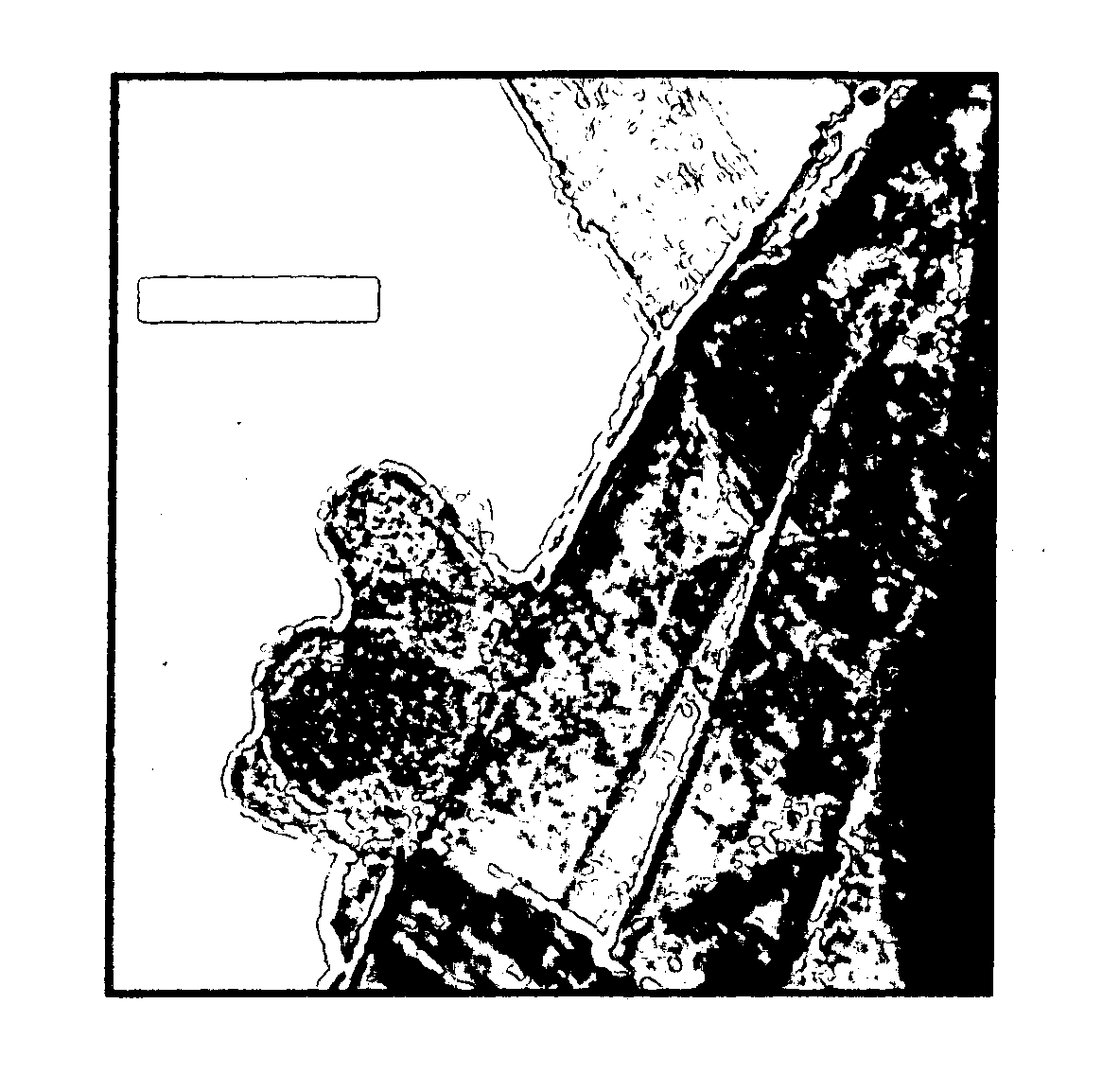
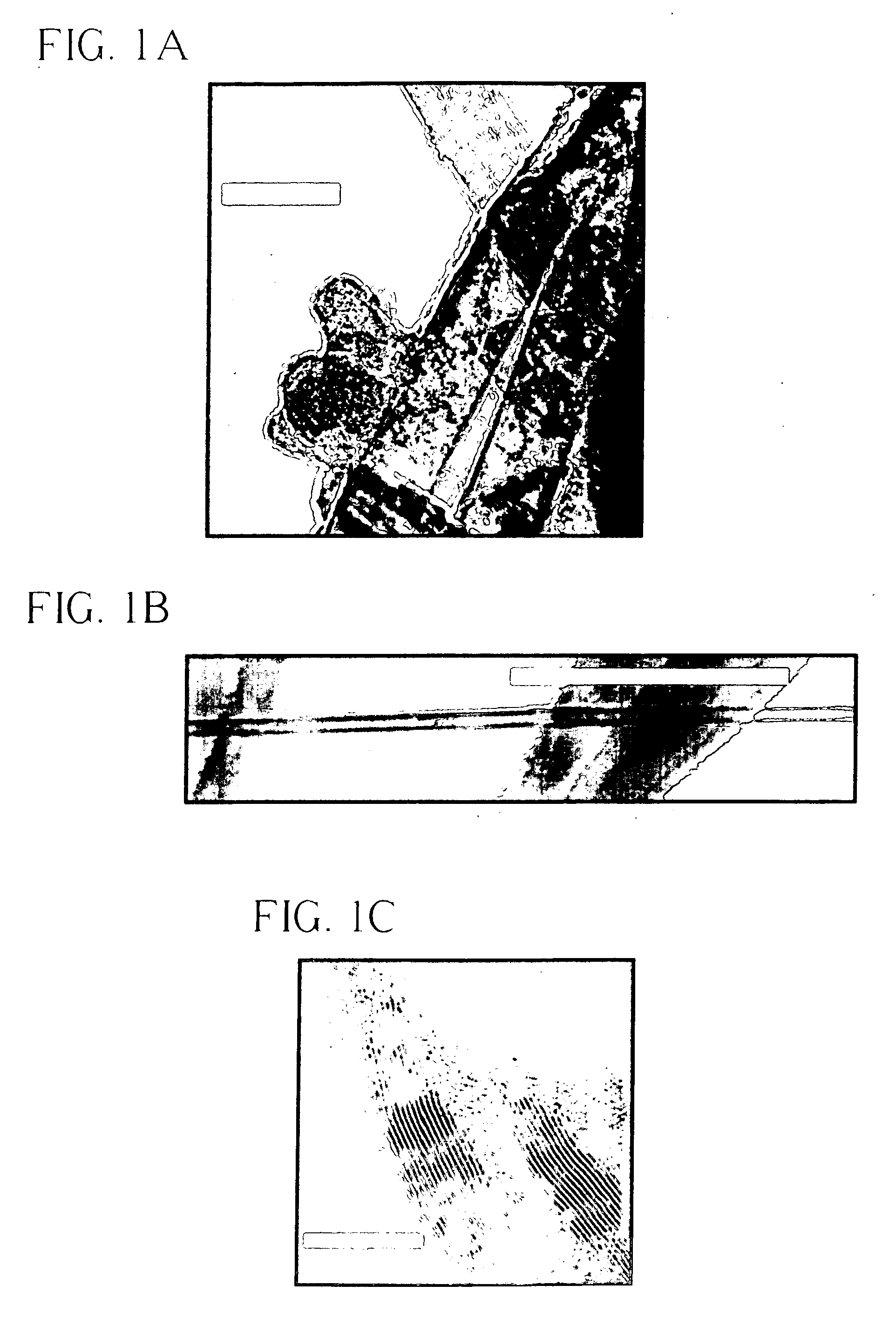
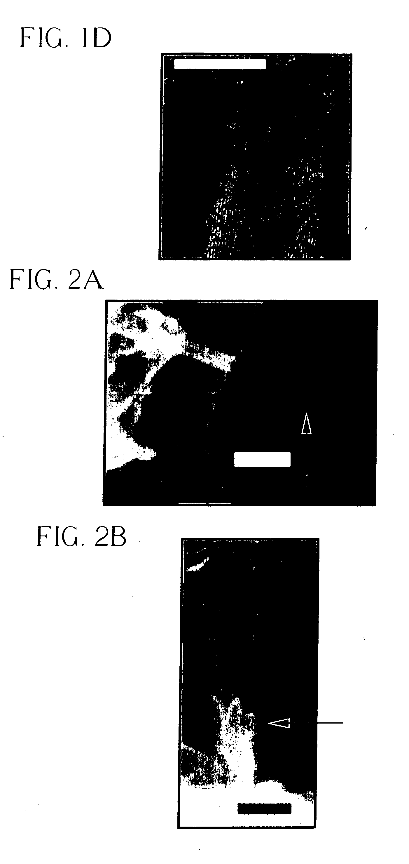
  • Fused carbon nanotube-nanocrystal heterostructures and methods of making the same
  • Fused carbon nanotube-nanocrystal heterostructures and methods of making the same
  • Fused carbon nanotube-nanocrystal heterostructures and methods of making the same

Examples


example 1

Synthesis of Multiwalled Nanotube Heterostructures Comprising CdTe Nanocrystals.

[0151] Multiwalled nanotubes (MWNTs) were obtained from MER Corporation. An aggressive functionalization protocol was used to remove almost all of the metal impurities (such as iron) and a substantial portion of the amorphous carbon entities in the sample (Hiura et al. Adv. Mater. (Weinheim, Ger.) 7:275 (1995). In essence, a vigorous KMnO4 / H2SO4 treatment was followed by successive processing with solutions of 35% HCl and 10% HF. The purified tubes were then extensively washed with distilled water and heated at 150° C. in a drying oven. XPS analysis, coupled with EDS data, have indicated that any remaining metal was below detectable limits.

[0152] This, rigorous functionalization protocol opens and derivatizes most of the nanotube ends as well as attacks occasional defect sites at the sidewalls (Hirsch, A. Angew. Chem., Int. Ed. 41:1853 (2002) and Banerjee et al. Chem. Eur. J. 9:1898 (2003)). The gener...

example 2

Synthesis of Single-Walled Nanotube Heterostructures Comprising CdTe Nanocrystals.

[0168] Nanotubes were ozonized and oxidized as described in Banerjee et al. J. Phys. Chem B 106:12144 (2002).

[0169] CdO was dissolved in TOPO at 320° C. in the presence of ozonized, oxygenated, and sidewall-functionalized HiPco (high-pressure CO conversion) SWNTs. A substoichiometric amount of tetradecylphosphonic acid (TDPA) was used so that some of the Cd precursor could complex with the tube surface. A solution of tellurium in trioctyl phosphine was rapidly injected at 270° C. and the QDs were allowed to grow at 250° C. under vigorous stirring for 1-20 min. In subsequent workup and purification, toluene was added at 50° C., followed by methanol, which precipitated CdTe nanocrystals in solution. After filtration over a 0.2 μm poly(tetrafluoroethylene) (PTFE) membrane and extensive washing with toluene to remove all unattached nanocrystals, the remaining dark residue was then dried and characterize...

example 3

Synthesis of Single-Walled Nanotube Heterostructures Comprising CdSe Nanocrystals.

[0176] Nanotubes were ozonized and oxidized as described in Banerjee et al. J. Phys. Chem B 106:12144 (2002).

[0177] Covalent sidewall functionalization of SWNTs was achieved by an initial treatment with ozone, followed by primary ozonide cleavage with hydrogen peroxide. (See U.S. application Ser. No. 10 / 701,402, incorporated herein by reference.) Carboxylic acids are expected as the predominant functional group on the heavily oxidized nanotube sidewalls. These functional groups, collectively covering up to 30% of the external nanotube surface sites, now act as reactive sites to coordinate onto organometallic metal precursors to CdSe quantum dot formation. Briefly, CdO was dissolved in trioctylphosphine oxide (TOPO) at 320° C., in the presence of ozone / H2O2 treated HiPco (high-pressure CO decomposition) SWNTs. A substoichometric amount of tetradecylphosphonic acid (TDPA) was used to facilitate solubi...


PUM

PropertyMeasurementUnit
diameteraaaaaaaaaa
diameteraaaaaaaaaa
diameteraaaaaaaaaa

Abstract

The present invention provides a fused heterostructure comprising a carbon nanotube and at least one nanocrystal, wherein the nanocrystal is attached by a covalent linkage to at least one oxygen moiety on the nanotube, and wherein there is no intermediary linker between the nanotube and the nanocrystal.

Description

BACKGROUND OF THE INVENTION [0001] The present invention relates to the art of nanotechnology, and in particular, to carbon nanotube technology, its function and structure. [0002] A carbon nanotube is a single graphene sheet in the form of a seamless cylinder. The ends of a nanotube typically have hemispherical caps. The typical diameter of a nanotube ranges from about 1 nm to 10 nm. The length of a nanotube potentially can be millions of times greater than its diameter. [0003] Carbon nanotubes are comprised of shells of sp2-hybridized carbon atoms forming a hexagonal network that is itself arranged helically within the cylinder. Basically, helicity is the arrangement of the carbon hexagonal rings with respect to a defined axis of a tube. (M. S. Dresselhaus et al “Science of Fullerenes and Carbon Nanotubes” (Academic Press, New York, 1996)). [0004] Carbon nanotubes are grown by combining a source of carbon with a catalytic nanostructured material such as iron or cobalt at elevated t...

Claims


Application Information

Patent Timeline
Patent Type & Authority Applications(United States)
IPC IPC(8): B32B9/00
CPCB82B1/00B82Y10/00B82Y30/00B82Y40/00C01B31/0253C01B2202/02Y10T428/30C01B2202/22C01B2202/36C30B29/60C30B29/602H01L51/0049Y10S977/742C01B2202/06C01B32/168H10K85/225
Inventor WONG, STANISLAUS S.BANERJEE, SARBAJIT
Owner THE RES FOUND OF STATE UNIV OF NEW YORK
Learn More