Measuring cell for ion cyclotron resonance mass spectrometer

a mass spectrometer and cyclotron technology, applied in mass spectrometers, omegatrons, separation processes, etc., can solve the problems of reducing the usable volume of the measuring cell, the frequency shift of the cyclotron frequency, and the electric field outside the axis of the measuring cell is more complicated to describe, so as to increase the mass resolution and mass accuracy

Active Publication Date: 2006-02-09
BRUKER DALTONIK GMBH & CO KG
View PDF5 Cites 19 Cited by
  • Summary
  • Abstract
  • Description
  • Claims
  • Application Information

AI Technical Summary

Benefits of technology

[0019] The invention provides a measuring cell whose trapping electrodes at the ends of the measuring cell consist of fine structural elements, adjacent structural elements each being connected to different phases of an RF voltage, thus generating repelling pseudopotentials and facilitating a cyclotron motion of the ions without magnetron motion. The measuring cell a

Problems solved by technology

The electric field outside the axis of the measuring cell is more complicated to describe.
The superposition of magnetron and cyclotron circular motion is an undesirable phenomenon which leads to a frequency shift in the cyclotron frequency.
Furthermore, it leads to a reduction in the usable volume of the measuring cell.
The loss of phase homogeneity leads to a reduction in the image currents and to a continuous decrease in the signal-to-noise-ratio, which reduces the usable measuring period.
Apart from the vacuum, the space charge in the ion cloud can also adversely affect the measurement.
The Coulombic repulsion between the ions themselves and, above all, the elastic reflection of the ions moving in the cloud lead to

Method used


Image

  • Measuring cell for ion cyclotron resonance mass spectrometer
  • Measuring cell for ion cyclotron resonance mass spectrometer
  • Measuring cell for ion cyclotron resonance mass spectrometer

Examples


Embodiment Construction

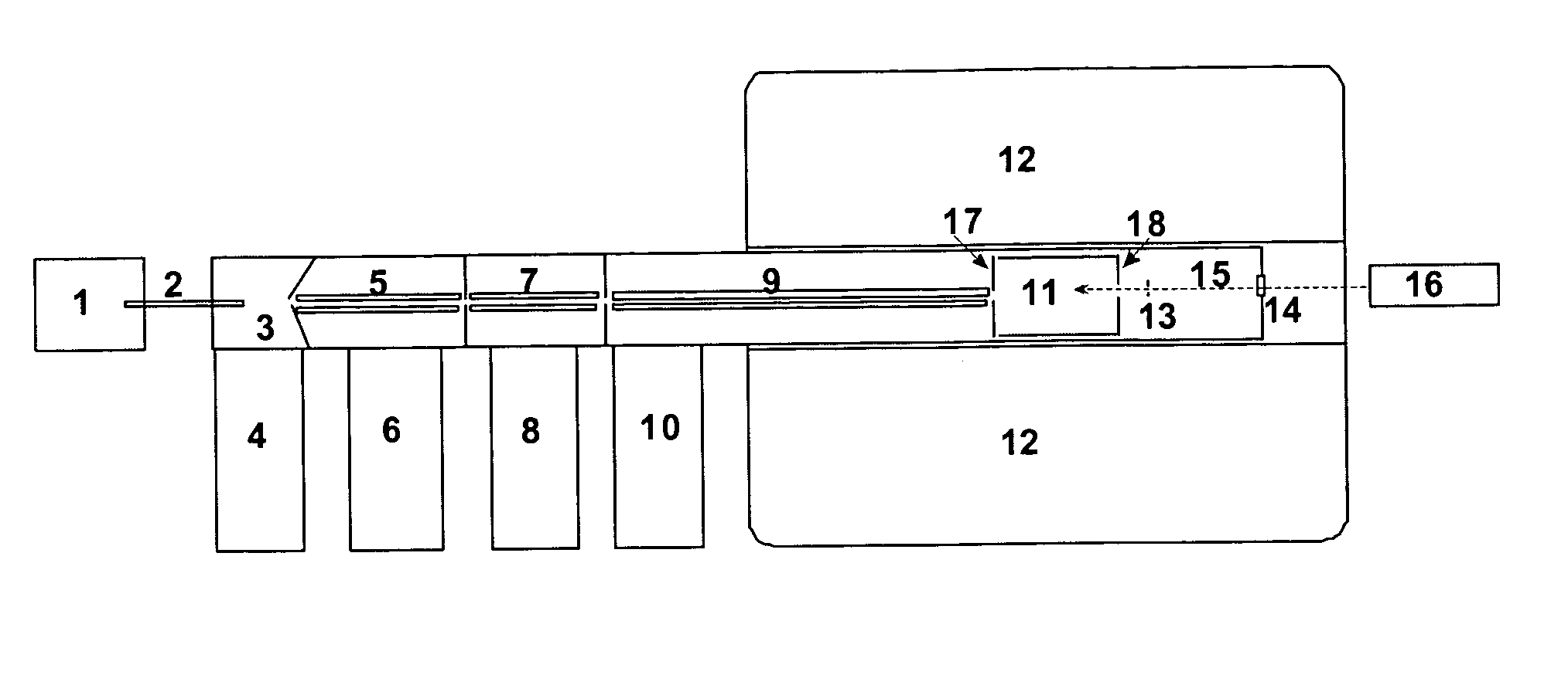
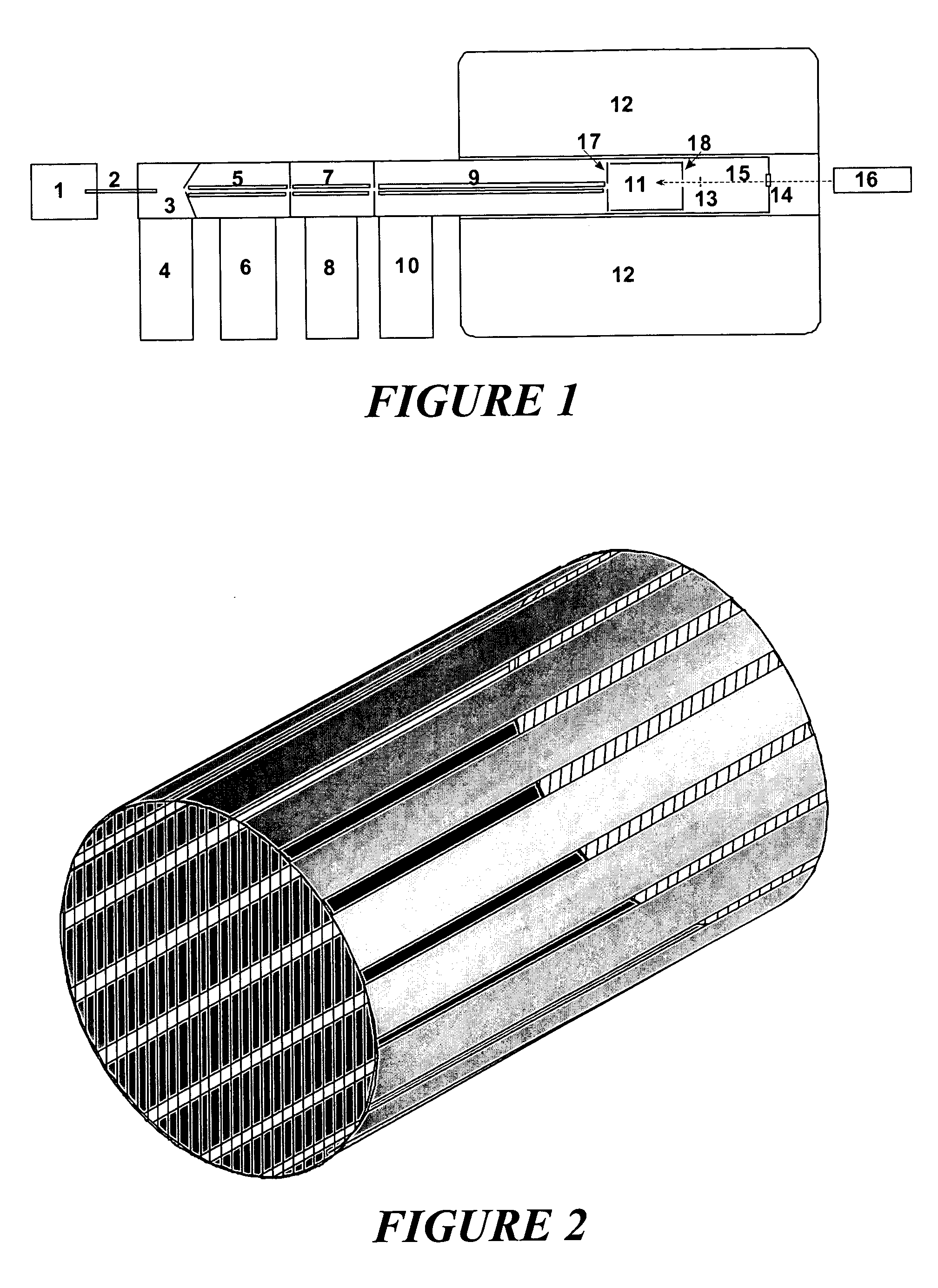
[0037] The operation and function of an ion cyclotron resonance mass spectrometer can be explained in more detail with the help of FIG. 1. The ions are, for example, generated by electrospray ionization in an out-of-vacuum ion source (1) and introduced together with ambient gas through a capillary (2) into the first stage (3) of a differential pump system, which comprises the chambers (3), (5), (7) and (9) and is evacuated by the pumps (4), (6), (8) and (10). The ions are collected by the ion guides (5), (7) and (9) and guided to the measuring cell (11), where they are confined. The measuring cell (11) usually consists of four longitudinal electrodes arranged to form a sliced cylinder and of two trapping electrodes (17) and (18), each having a central aperture. The measuring cell is located in the homogeneous region of a strong magnetic field generated by superconductive coils in a helium cryostat (12) and has a magnetic field strength of high constancy. Electrons can be generated b...


PUM


Abstract

The invention relates to a measuring cell for an ion cyclotron resonance mass spectrometer (FTMS). The invention provides a measuring cell which, on the one hand, consists of two ion-repelling RF grids at the front ends as trapping electrodes and thus produces a pure cyclotron motion of the ions without the usually co-existing magnetron motion and, on the other hand, measures a multiplied cyclotron frequency by means of a plurality of detection electrodes, whereby either a higher mass accuracy or a shorter measuring time can be achieved.

Description

FIELD OF THE INVENTION [0001] The invention relates to a measuring cell for an ion cyclotron resonance mass spectrometer (FTMS). BACKGROUND OF THE INVENTION [0002] In ion cyclotron resonance mass spectrometers (ICR-MS), the mass-to-charge ratios m / z of ions are measured by their cyclotron movements in a homogeneous magnetic field with high field strength. The magnetic field is usually generated by superconductive magnetic coils cooled in liquid helium. Nowadays, they provide usable cell diameters of around 6 to 12 centimeters at magnetic field strengths of 7 to 12 Tesla. [0003] The orbital frequency of the ions (ion cyclotron frequency) is measured in ICR measuring cells located within the homogeneous part of the magnetic field. The ICR measuring cells normally comprise four longitudinal electrodes which extend in a cylindrical arrangement parallel to the magnetic field lines and surround the measuring cell like a sliced sleeve. Usually, two of these electrodes are used to bring ion...

Claims


Application Information

Patent Timeline
IPC IPC(8): H01J49/40B01D59/44H01J49/38
CPCH01J49/38
Inventor FRANZEN, JOCHENNIKOLAEV, EVGENIJ
Owner BRUKER DALTONIK GMBH & CO KG
Why Eureka
Try Eureka