Apparatus for electro-blowing or blowing-assisted electro-spinning technology and process for post treatment of electrospun or electroblown membranes

a technology of electro-spinning and apparatus, which is applied in the direction of auxillary shaping apparatus, butter manufacture, filament/thread forming, etc., can solve the problems of low yield of the electro-spinning process, low speed of fabrication of nanofibers, and limitation of the minimum separation distance between the electrodes or the maximum density of the spinneret, etc., to achieve the effect of high throughpu

Inactive Publication Date: 2006-03-09
THE RES FOUND OF STATE UNIV OF NEW YORK
View PDF11 Cites 87 Cited by
  • Summary
  • Abstract
  • Description
  • Claims
  • Application Information

AI Technical Summary

Benefits of technology

[0020] Accordingly, one object of the present invention is to provide a spinneret assembly for forming a polymer fiber, which is

Problems solved by technology

The major technical barriers for manufacturing nanofibers by electro-spinning are the low speed of fabrication and the limitation of process to polymer solutions, which can be summarized as follows: 1.
The first barrier involves electrical field interferences between adjacent electrodes (or spinning jets), which limit the minimum separation distance between the electrodes or the maximum density of spinnerets that can be constructed in the multiple jet electro-spinning die block.
In other words, as the fiber size becomes very small, the yield of the electro-spinning process becomes very low.
The third barrier is limited by the capability for continuous operation over extended periods of time and automatic cleaning of multiple spinnerets with minimal labor involvement.
The last barrier of electro-spinning is due to the limitation of solution processing, where the use of solvent severely hinders the industrial applicability of the technique.
However, there are several drawbacks in this disclosed technology.
It does not fully utilize the electrical field to achieve a sufficiently large spin-draw ratio during blowing, thus, they cannot produce smaller size diameter fibers (e.g., fibers of less than 300 nm in diameter).
It cannot sustain a long-term operation capability (e.g., >5 days) because the unavoidable polymer

Method used


Image

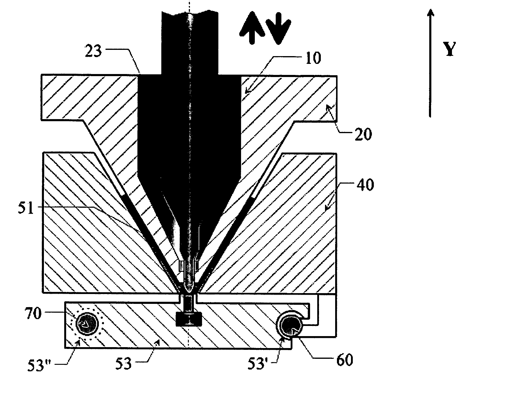
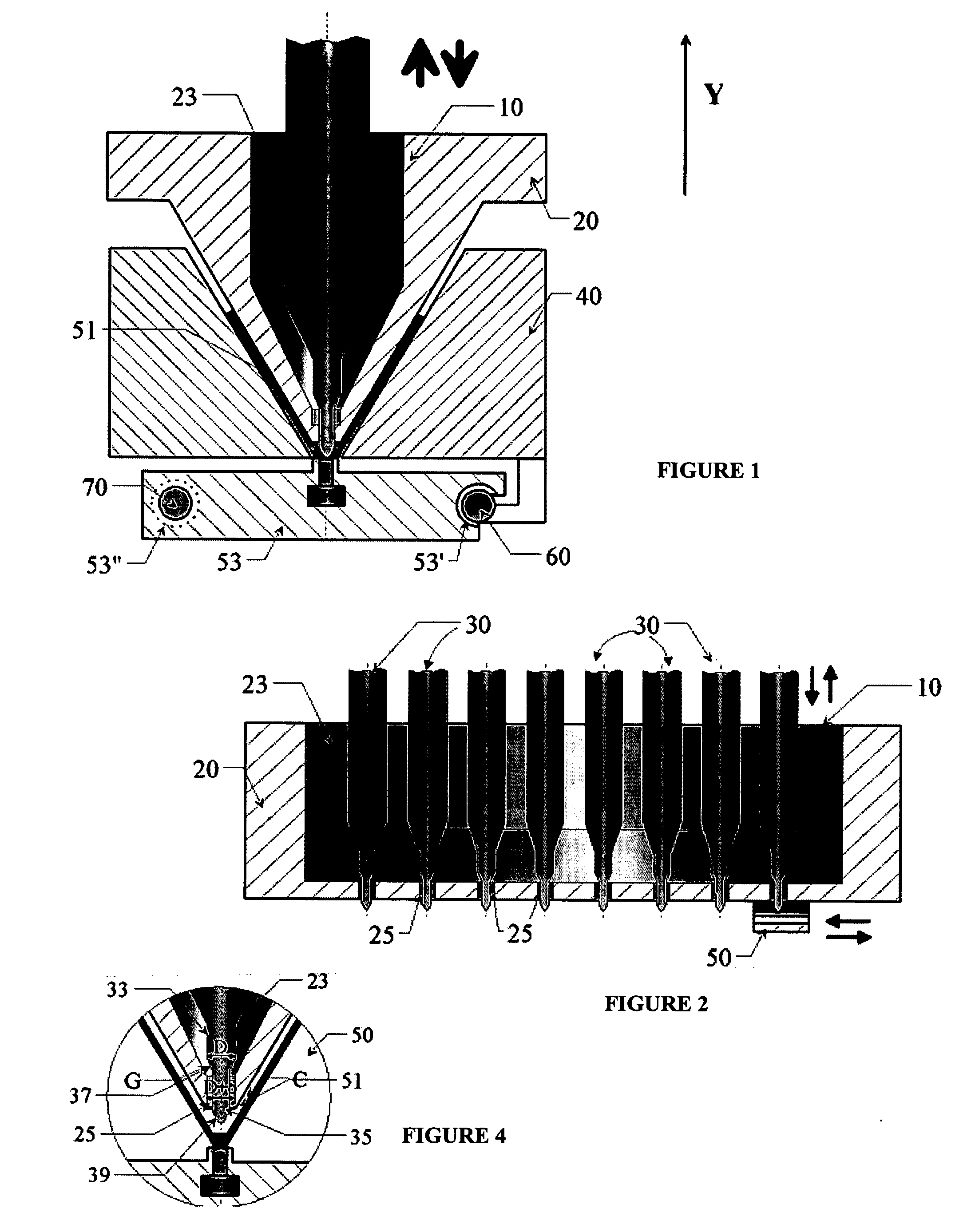
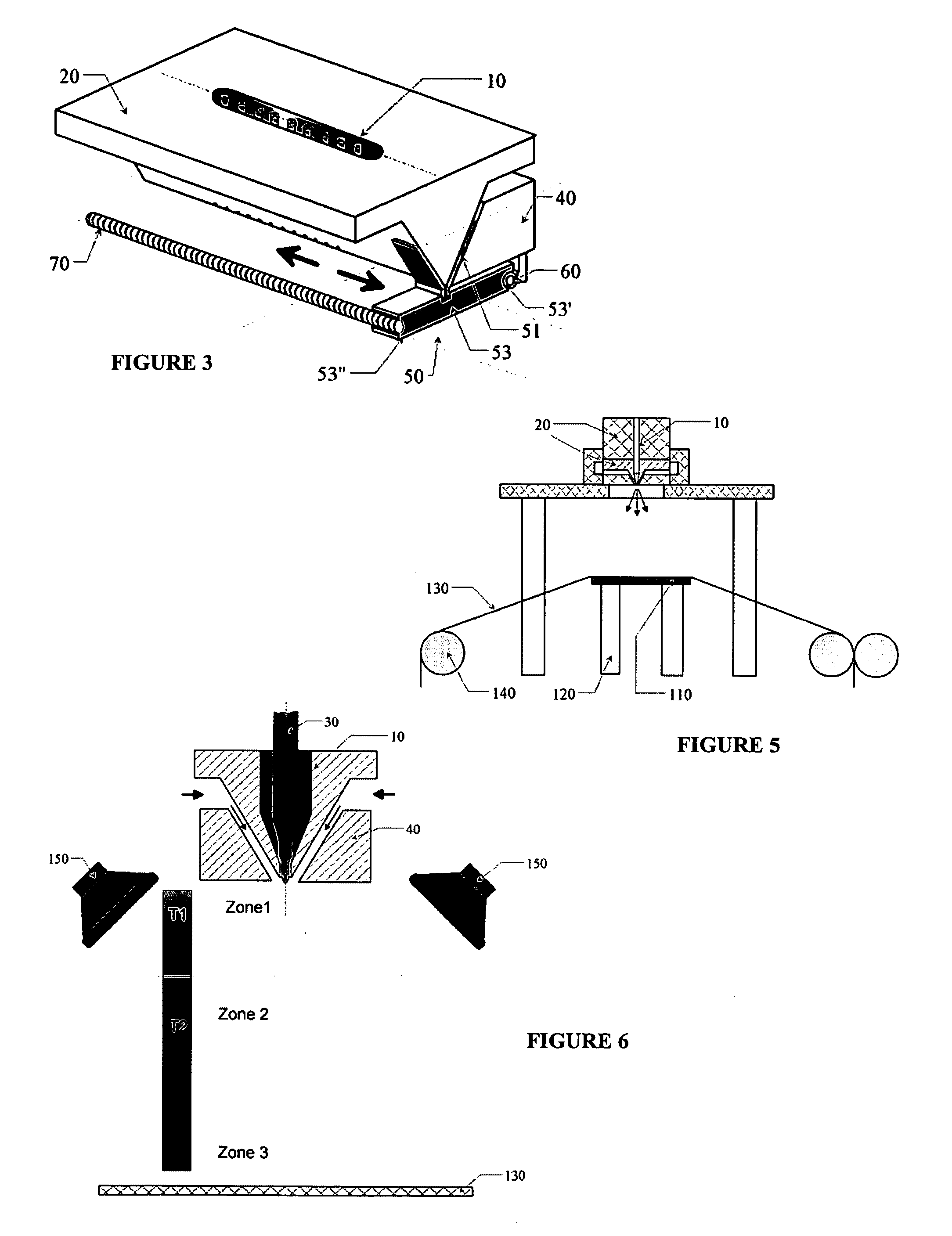
  • Apparatus for electro-blowing or blowing-assisted electro-spinning technology and process for post treatment of electrospun or electroblown membranes
  • Apparatus for electro-blowing or blowing-assisted electro-spinning technology and process for post treatment of electrospun or electroblown membranes
  • Apparatus for electro-blowing or blowing-assisted electro-spinning technology and process for post treatment of electrospun or electroblown membranes

Examples


examples

[0129] Having generally described the invention, further understanding can be obtained by reference to certain specific examples, which are provided herein for purposes of illustration only and are not intended to be limiting unless otherwise specified.

Instrumentation Development

[0130] Two prototypes of multiple jet electro-blowing apparatuses were constructed in accordance with the present invention. The first prototype device involved the use of the patented esJets™ technology with secondary electrodes to shield each primary electrode during multiple jet electro-spinning for polymer solutions. Since the presence of secondary electrodes can weaken the field strength at the electrode tip, the geometrical shape, the location and the electric potential of the secondary electrodes, were optimized by finite element analysis simulations. The following two criteria were met simultaneously in the design: (1) each electrode in the multi jet system essentially had the same electric field ...


PUM

PropertyMeasurementUnit
Fractionaaaaaaaaaa
Electric chargeaaaaaaaaaa
Temperatureaaaaaaaaaa

Abstract

A spinneret format, an electric-field reversal format and a process for post-treatment of membranes formed from electro-spinning or electro-blowing are provided, including a cleaning method and apparatus for electro-blowing or blowing-assisted electro-spinning technology.

Description

BACKGROUND OF THE INVENTION [0001] 1. Field of Invention [0002] The present invention relates to electro-blowing or blowing-assisted electro-spinning technology, and more particularly to a spinneret format and to a process for post-treatment of membranes formed from such technology, including a cleaning method and apparatus for electro-blowing or blowing-assisted electro-spinning technology. [0003] 2. Discussion of the Background [0004] One technique conventionally used to prepare fine polymer fibers is the method of electro-spinning. When an external electrostatic field is applied to a conducting fluid (e.g., a charged semi-dilute polymer solution or a charged polymer melt), a suspended conical droplet is formed, whereby the surface tension of the droplet is in equilibrium with the electric field. Electro-spinning occurs when the electrostatic field is strong enough to overcome the surface tension of the liquid. The liquid droplet then becomes unstable and a tinyjet is ejected from...

Claims


Application Information

Patent Timeline
IPC IPC(8): B29C47/60
CPCD01D5/0092D01D4/04D01D5/0069
Inventor CHU, BENJAMINHSAIO, BENJAMIN S.FANG, DUFEI
Owner THE RES FOUND OF STATE UNIV OF NEW YORK
Why Eureka
Try Eureka