Negative electrode for non-aqueous electrolyte secondary cell and method for manufacture thereof, and non-aqueous electrolyte secondary cell

a secondary cell and negative electrode technology, applied in the direction of secondary cell servicing/maintenance, cell components, cell component details, etc., can solve the problems of not being put to practical use, difficult to meet the increasing demands in the near future, and the power consumption of these devices has shown a remarkable increase. , to achieve the effect of improving the electrical conductivity of the negative electrode, improving the electron conductivity, and improving the electrical conductivity

Inactive Publication Date: 2006-03-09
MITSUI MINING & SMELTING CO LTD
View PDF2 Cites 65 Cited by
  • Summary
  • Abstract
  • Description
  • Claims
  • Application Information

AI Technical Summary

Benefits of technology

[0022] The active material layer 3 is a layer containing active material particles 7 which have a material having high capability of forming a lithium compound. Such a material includes silicon materials, tin materials, aluminum materials, and germanium materials. The maximum particle size of the active material particles 7 is preferably 50 μm or smaller, still preferably 20 μm or smaller. The particle size, represented in terms of D50 value, of the active material particles 7 is preferably 0.1 to 8 μm, still preferably 0.3 to 1 μm. Where the maximum particle size exceeds 50 μm, the active material particles 7 are liable to fall off, resulting in reduction of electrode life. The lower limit of the particle size is not particularly specified. The smaller, the better. In the light of the process of making the active material particles 7 (described later), the lower limit would be about 0.01 μm. The particle size of the active material particles 7 can be measured by Microtrac, electron microscopic (SEM) observation. While it is desirable that all the active material particles 7 fall under the recited particle size range, it is no problem that greater active material particles 7 are present in a small amount that does not impair the effects of the invention.
[0023] It is preferred that voids be present in the active material layer 4. The voids serve to relax the stress which results from expansion and contraction of the active material particles 7 due to intercalation and deintercalation of lithium. In this connection, the proportion of the voids in the active material layer 4 is preferably about 1 to 30% by volume, still preferably about 5 to 30% by volume, particularly preferably about 5 to 9% by volume. The proportion of the voids is obtained through mapping under an electron microscope. The proportion of the voids can be regulated within the recited range by forming the active material layer by the process described later, followed by mechanically pressing the active material layer under appropriate conditions.
[0024] The active material layer 4 preferably contains an electro-conductive carbon material in addition to the active material particles 7. Incorporation of the conductive carbon material adds improved electron conductivity to the active material structure 5. From this viewpoint, the amount of the conductive carbon material in the active material layer 3 is preferably 0.1 to 20% by weight, still preferably 1 to 10% by weight. To ensure the improvement on electron conductivity, it is preferred for the electro-conductive carbon material to have the shape of particles with a particle size of 40 μm or smaller, particularly 20 μm or smaller. The lower limit of the particle size is not critical, which means the smaller, the better. In the light of the process of making the particles, the lower limit would be about 0.01 μm. The conductive carbon material includes acetylene black and graphite.
[0025] The surface coating layer 4 is a thick layer continuously covering the surface of the active material layer 3, thereby the active material particles 7 are not substantially exposed. The surface coating layer 4 generally covers the surface of the active material layer 3. The surface coating layer 4 has an almost uniform thickness, but some part 4a of the surface coating layer 4 may enter into the active material layer 3. Some part of the surface coating layer 4 penetrating the active material layer 3 may reach the current collector 2. In some parts, the material constituting the surface coating layer 4 may penetrate the whole thickness of the active material layer 3 to reach the current collector. It is preferred that the material constituting the surface coating layer 4 penetrate the active material layer 3 deeper and deeper thereby increasing the electrical conductivity of the negative electrode as a whole. This is also preferred in that the penetrating material constituting the surface coating layer 4 forms a network structure and acts to prevent the active material particles 7 from falling off due to expansion and contraction.
[0026] The active material particles 7 do not always need to be covered completely with the surface coating layer 4, and part of them may be exposed. Taking into consideration, however, that the active material particles 7 should be prevented from falling off as a result of pulverization due to intercalation and deintercalation of lithium, it is desirable that the active material particles 7 be completely covered with the surface coating layer 4. Even though the active material particles 7 are completely covered with the surface coating layer 4, an electrolyte and lithium are allowed to penetrate through micropores 6 (described infra) into the inside of the surface coating layer 4 and to react with the active material particles 7.
[0027]FIGS. 3 and 4 represent different examples of the negative electrode in which the active material layer 3 is completely covered with the surface coating layer 4. In FIGS. 3 and 4, the active material layer 3 formed on the current collector 1 that is copper, contains silicon-copper alloy particles, and the surface coating layer 4 that is copper is located on the active material layer 3. The active material layer 3 is completely covered with the surface coating layer 4. In the surface coating layer 4 are observable fine breaks extending in the thickness direction. Voids among alloy particles are observable in the active material layer 3. In FIG. 3, it is seen that part of the surface coating layer 4 goes into the active material layer 3 to such a degree that an alloy particle is surrounded with copper. In FIG. 4, on the other hand, the surface coating layer 4 is not so invasive into the active material layer 3, and the two layers 3 and 4 are defined relatively clearly. Such a difference in layer geometry is ascribed to the process of producing the negative electrode.

Problems solved by technology

With the latest tendency of mobile phones and personal computers toward multifunctionality, power consumption of these devices has shown a remarkable increase.
As long as the present electrode active materials are used, it would be difficult to meet the increasing demands in the near future.
While these alloys have high capacity, they have not yet been put to practical use on account of the problems of large irreversible capacity and short cycle life.
On the other hand, though silicon has higher capacity potential than tin, there is no report on the development of silicon-containing plated copper foil for use in lithium ion secondary batteries because silicon is an element incapable of electroplating.
However, they have the drawback that they incur large changes in volume with alternate repetition of charging and discharging and, as a result, undergo cracking and pulverizing and finally fall off the current collector.
Even with these techniques, however, it is still impossible to perfectly prevent fall-off of the negative electrode active material from the current collector as a result of cracking and pulverizing of the active material, accompanying charge and discharge of a secondary battery.
Judging from Examples of the publication, however, since the thickness of the layer of the metallic element incapable of forming a lithium alloy, which is the outermost layer, is as extremely small as 50 nm, there is a possibility that the outermost layer fails to sufficiently coat the underlying layer containing the lithium alloy-forming metal element.
If so, the layer containing the metallic element capable of forming a lithium alloy cannot be sufficiently prevented from falling off when pulverized with repeated charging and discharging of the battery.
Conversely, if the layer of the metal element incapable of forming a lithium alloy completely covers the layer containing the lithium alloy-forming metal element, the former layer would inhibit an electrolyte from passing through the latter layer, which will interfere with sufficient electrode reaction.
No proposal has ever been made to satisfy these conflicting functions.
However, since the oxide film comes off little by little, together with the foil, it is difficult to control the porosity and pore size.
There seems to be a limit, therefore, in improving the adhesion between the paste and the foil.
According to the process of making the porous copper foil, however, the electrolytic copper foil deposited on a cathode drum and separated from the drum, is subjected to various processing treatments, which make the copper foil unstable.
Therefore, the process cannot be seen as satisfactory in ease of handling the foil and fit for large volume production.
Additionally, a nonaqueous secondary battery using a negative electrode, prepared by applying a negative electrode active material mixture to the porous copper foil (a current collector), still has the problem that the negative electrode active material tends to fall off accompanying intercalation and deintercalation of lithium, resulting in reduction of cycle characteristics.

Method used


Image

  • Negative electrode for non-aqueous electrolyte secondary cell and method for manufacture thereof, and non-aqueous electrolyte secondary cell
  • Negative electrode for non-aqueous electrolyte secondary cell and method for manufacture thereof, and non-aqueous electrolyte secondary cell
  • Negative electrode for non-aqueous electrolyte secondary cell and method for manufacture thereof, and non-aqueous electrolyte secondary cell

Examples


example 1-1

(1) Preparation of Active Material Particles

[0098] A molten metal at 1400° C. containing 90% of silicon and 10% of nickel was cast into a copper-made mold and quenched to obtain an ingot of a silicon-nickel alloy. The ingot was pulverized and sieved to obtain silicon-nickel alloy particles having particle sizes of 0.1 to 10 μm. The silicon-nickel alloy particles and nickel particles (particle size: 30 μm) were blended at a rate of 80% 20% and mixed and pulverized simultaneously in an attritor to obtain uniformly mixed particles of silicon-nickel particles and nickel. The mixed particles had the maximum particle size of 1 μm and a D50 value of 0.8 μm.

(2) Preparation of Slurry

[0099] A slurry having the following composition was prepared.

Mixed particles obtained in (1) above16%Acetylene black (particle size: 0.1 μm)2%Binder (polyvinylidene fluoride)2%Diluting solvent (N-methylpyrrolidone)80%

(3) Formation of Active Material Layer

[0100] The above prepared slurry was applied to a...

examples 1-2 to 1-4

[0103] A negative electrode was produced in the same manner as in Example 1-1, except for using the active material particles shown in Table 1-1 below. The same electron microscopic observation as in Example 1-1 revealed presence of micropores in the resulting negative electrode.

example 1-5

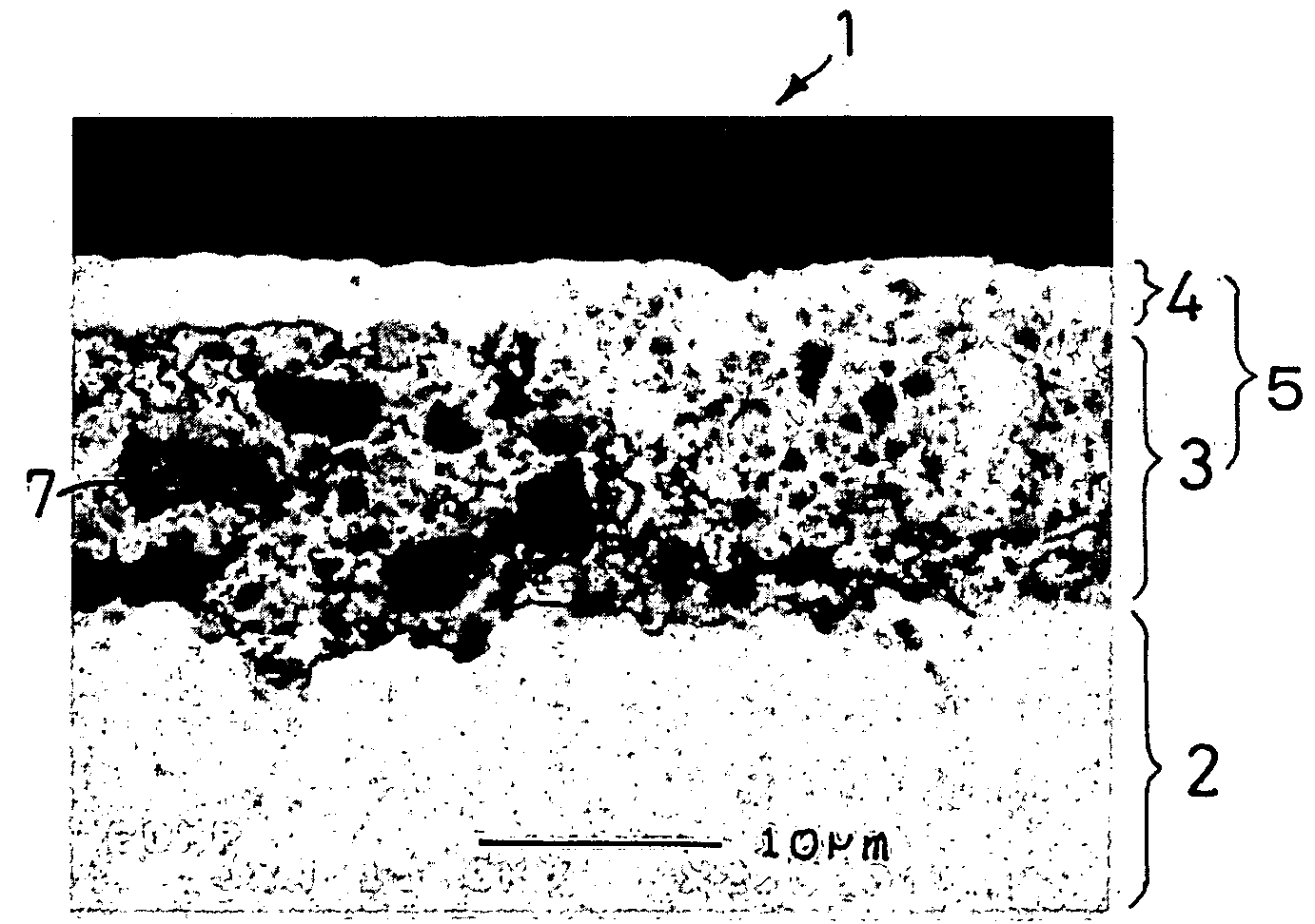
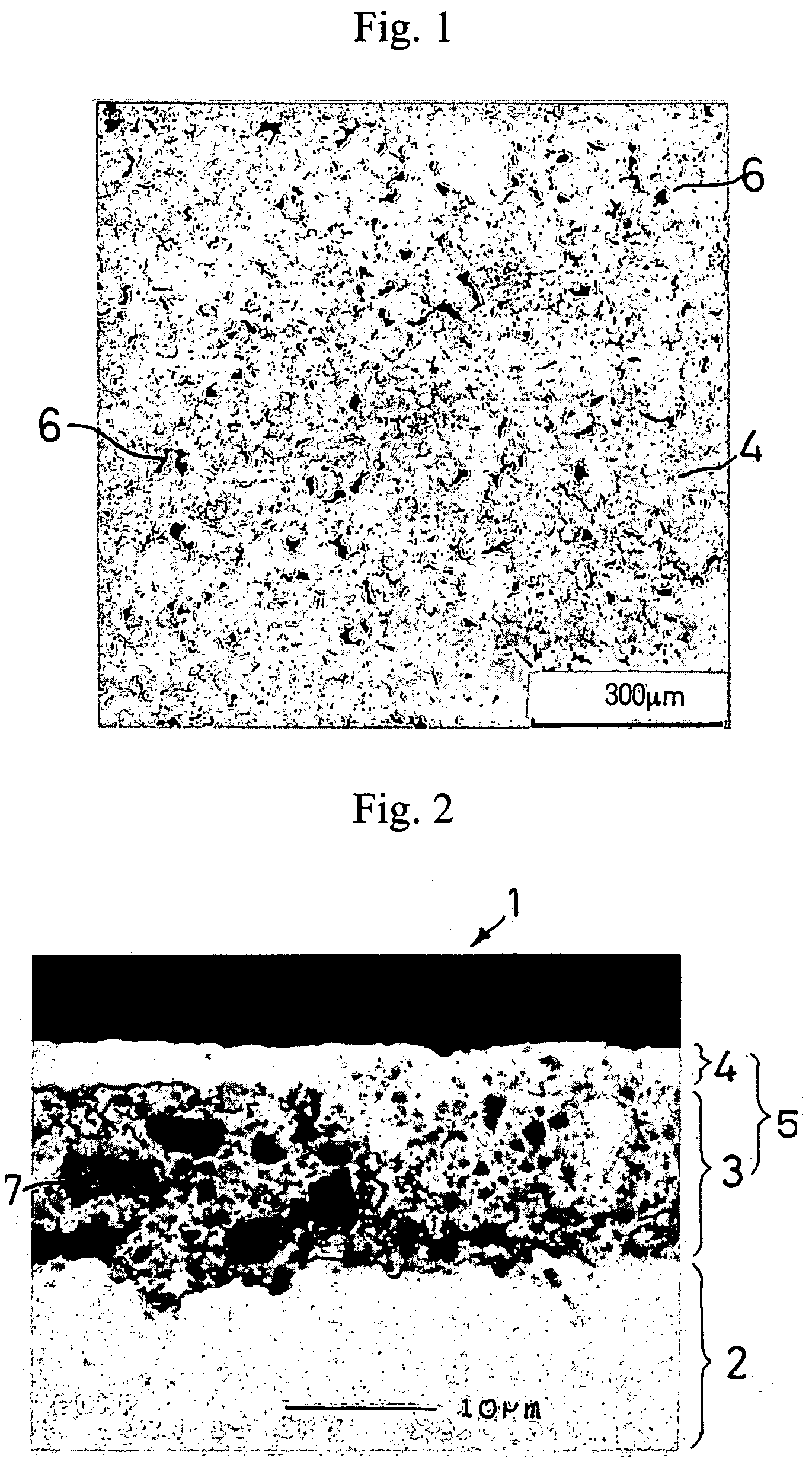
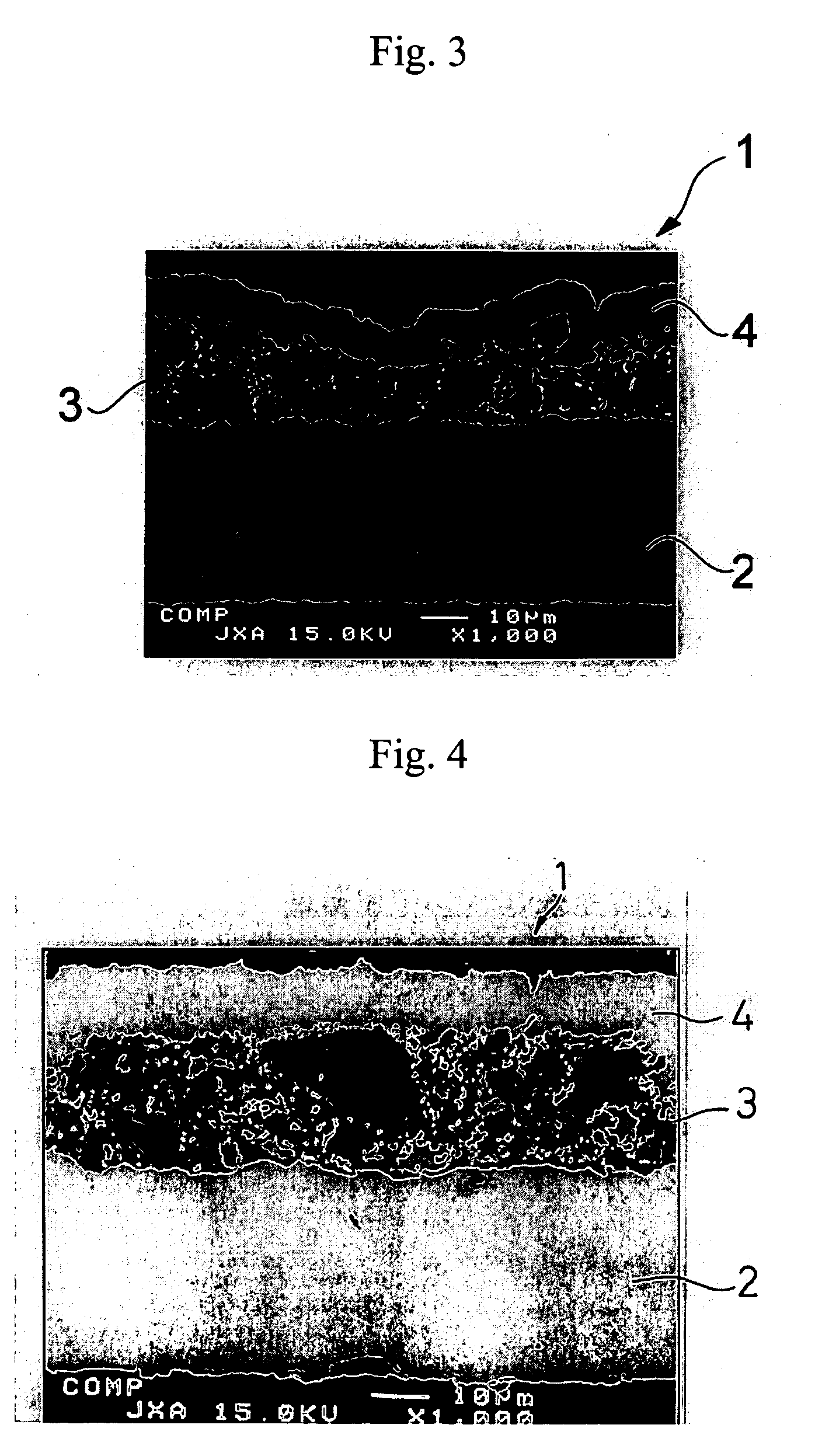
[0104] A 35 μm thick copper foil was plated with nickel to a deposit thickness of 2 μm to prepare a current collector. An active material layer and a surface coating layer were formed on the nickel layer in the same manner as in Example 1-1, except for using the active material particles shown in Table 1-1 in the active material layer. The same electron microscopic observation as in Example 1-1 revealed presence of micropores in the resulting negative electrode.


PUM

PropertyMeasurementUnit
particle sizeaaaaaaaaaa
thicknessaaaaaaaaaa

Abstract

Disclosed is a negative electrode for a nonaqueous secondary battery included of a current collector and an active material structure containing an electro-conductive material having low capability of forming a lithium compound on at least one side of the current collector, the active material structure containing 5 to 80% by weight of active material particles containing a material having high capability of forming a lithium compound. The active material structure preferably has an active material layer containing the active material particles and a surface coating layer formed on the active material layer.

Description

TECHNICAL FIELD [0001] This invention relates to a negative electrode for nonaqueous secondary batteries. More particularly, it relates to a negative electrode capable of intercalating and deintercalating a large amount of lithium and providing a nonaqueous secondary battery with high energy density and improved cycle life. The present invention also relates to a nonaqueous secondary battery using the negative electrode. BACKGROUND ART [0002] Secondary batteries now used in mobile phones and notebook computers are mostly lithium ion secondary batteries, due to a higher energy density than other secondary batteries. With the latest tendency of mobile phones and personal computers toward multifunctionality, power consumption of these devices has shown a remarkable increase. Therefore, the demands for higher capacity secondary batteries have been increasing. As long as the present electrode active materials are used, it would be difficult to meet the increasing demands in the near futu...

Claims


Application Information

Patent Timeline
Patent Type & Authority Applications(United States)
IPC IPC(8): H01M4/58H01M4/62H01M2/16H01M4/02H01M4/134H01M4/1395H01M4/36H01M4/38H01M4/40H01M10/052H01M10/36
CPCH01M4/134H01M4/1395H01M4/366H01M4/38Y02E60/122H01M4/624H01M10/052H01M2004/027H01M4/405H01M4/386H01M4/387Y02E60/10H01M4/13
Inventor MUSHA, SHINICHIHONDA, HITOHIKOSAKAGUCHI, YOSHIKIYASUDA, KIYOTAKAMODEKI, AKIHIROMATSUSHIMA, TOMOYOSHITAGUCHI, TAKEOTANIGUCHI, KAZUKODOBASHI, MAKOTO
Owner MITSUI MINING & SMELTING CO LTD
Why Eureka
Try Eureka