Pixel control element selection transfer method, pixel control device mounting device used for pixel control element selection transfer method, wiring formation method after pixel control element transfer, and planar display substrate

Inactive Publication Date: 2006-03-16
MATSUMURA HIDEKI
View PDF16 Cites 322 Cited by
  • Summary
  • Abstract
  • Description
  • Claims
  • Application Information

AI Technical Summary

Benefits of technology

[0034] Thus, the transparent ultraviolet curing resin film is formed to cover the surfaces of the pixel control devices and the surface of the planar display substrate after the planar display substrate retains thereon the pixel control devices, and ultraviolet rays are then irradiated from the back surface side of the planar display substrate. Since the planar display substrate transparent in general transmits ultrasonic rays, the transparent ultraviolet curing resin film is cured over its entire portion other than the upper surfaces of the pixel control devices (the surfaces not in contact with the planar display substrate or transparent thermoplastic resin film). When the transparent ultraviolet curing resin film not cured on the upper surfaces of the pixel control devices is then removed, the transparent ultraviolet curing resin film cured with the ultraviolet rays is uniformly formed on the peripheral portions of the pixel control devices other than the upper surfaces thereof, with the result that wirings drawn out from the upper surfaces of the pixel control devices can stably be formed.
[0035] I

Problems solved by technology

However, it is intended to enlarge the display area to reply to a recent demand for display screen enlargement, the following problems have been raised.
The first problem is that the fabrication device, such as CVD device etc. for fabricating microelectronic devices on a planar display substrate, has to be inevitably enlarged with the enlargement of a planar display.
As a result, it is difficult to reduce the fabrication cost.
The second problem is that since an amorphous silicon (a-Si) film etc. that can be fabricated from a thin film that can be deposited at low temperature of around 300° C. the glass substrate can endure is used as a semiconductor film, the operation performance is inferior to that of semiconductor electronic devices using crystallized silicon.
Particularly in the display according to an organic EL that emits light by application of individually controlled electric currents through the respective pixels, it is generally confirmed that the operation performance of the a-Si TFT is insufficient.
However, since it highly costs to fabricate a laser-melted poly-Si film, it is premised that the application thereof is only in a restricted range.
Also in an a-Si TFT that has a display screen diagonal dimension of 40 inches or more, an a-Si film deposition step and the following pattern transfer step are difficult to take, and the cost for taking the steps becomes increased.
The third problem is that in displays using a glass plate as a substrate, when the display screen size is in the range of 40 to 100 inches, the thickness of the glass substrate has to be large enough to attain its sufficient strength.
This increases the entire display device weight and consequently requires a device structure to be enlarged in order to stably install the display device and raises the entire cost.
However, since the ratio of the number of the pixel control devices successfully fitted into the mold on the display substrate to the number of the pixel control devices poured together with the liquid is small, the prior art method is not put to practical use.
Furthermore, since a great number of pixel control devices are poured onto the display substrate in view of the small ratio, excess pixel control devices not fitted into the mold have to be recovered.
Moreover, since the pixel control devices when being poured together with the liquid and recovering the excess pixel control devices move directly in contact with the display substrate, there is a fair possibility of the pixel control devices damaging the display substrate.
This size difference causes displacement of the pixel control devices in the reces

Method used


Image

  • Pixel control element selection transfer method, pixel control device mounting device used for pixel control element selection transfer method, wiring formation method after pixel control element transfer, and planar display substrate
  • Pixel control element selection transfer method, pixel control device mounting device used for pixel control element selection transfer method, wiring formation method after pixel control element transfer, and planar display substrate
  • Pixel control element selection transfer method, pixel control device mounting device used for pixel control element selection transfer method, wiring formation method after pixel control element transfer, and planar display substrate

Examples


first embodiment

Method of Producing a Planar Display Substrate

[0087] (1. Structure of a Liquid Crystal Display)

[0088] In the present embodiment, a method for producing a planar display substrate according to the present invention is applied to the production of a liquid crystal display. A liquid crystal display 200 has a structure, as shown in FIG. 24, comprising a planar display substrate 100, a color filter substrate 111 and a liquid crystal 112 interposed between them. The planar display substrate of plastic (also called the first substrate or array substrate) 100 has a pixel control device 1 and transparent electrodes (pixels) 102 formed thereon via a resin film 101 in matrix form on which an orientation film 110 is formed. On the other hand, the color filter substrate 111 has a color filter 114 formed thereon via a solvent resistant layer 113 so that the color filter is opposed to the transparent electrodes 102. On the surface of the solvent resistant layer, a transparent electrode for color ...

second embodiment

Method of Producing a Planar Display Substrate

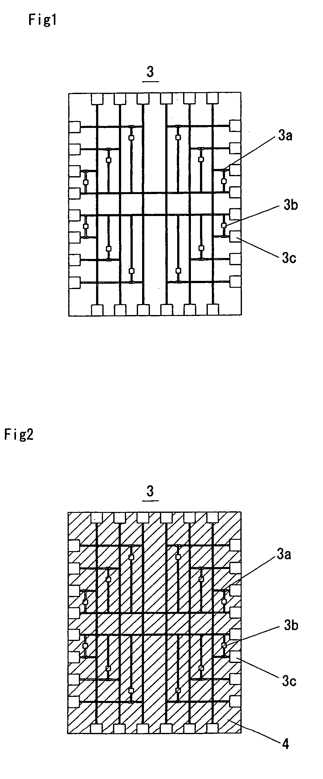
[0112] In the present embodiment, a transfer step R11 to the substrate 9 for pickup is performed as shown in the flow chart of FIG. 25 after the cutting step R10 for pixel control devices 1. After the mechanical polishing of the silicon substrate 2 shown in FIG. 6 at step R2, positional alignment of the integrated circuits 3 formed on the silicon substrate 2 and patterning of the pixel control devices 1 are conducted so that cutting can be established at step 10 between the integrated circuits 3. At this time, since the integrated circuits 3 exist not on the side of the front surface of the silicon substrate 1, but on the side in contact with the support substrate 7, the positional alignment cannot be conducted while discernibly confirming the positions thereof directly from above. Therefore, the positional alignment can be conducted through provision of position-aligning marks on the back surface 2b of the silicon substrate 2 or formati...

example

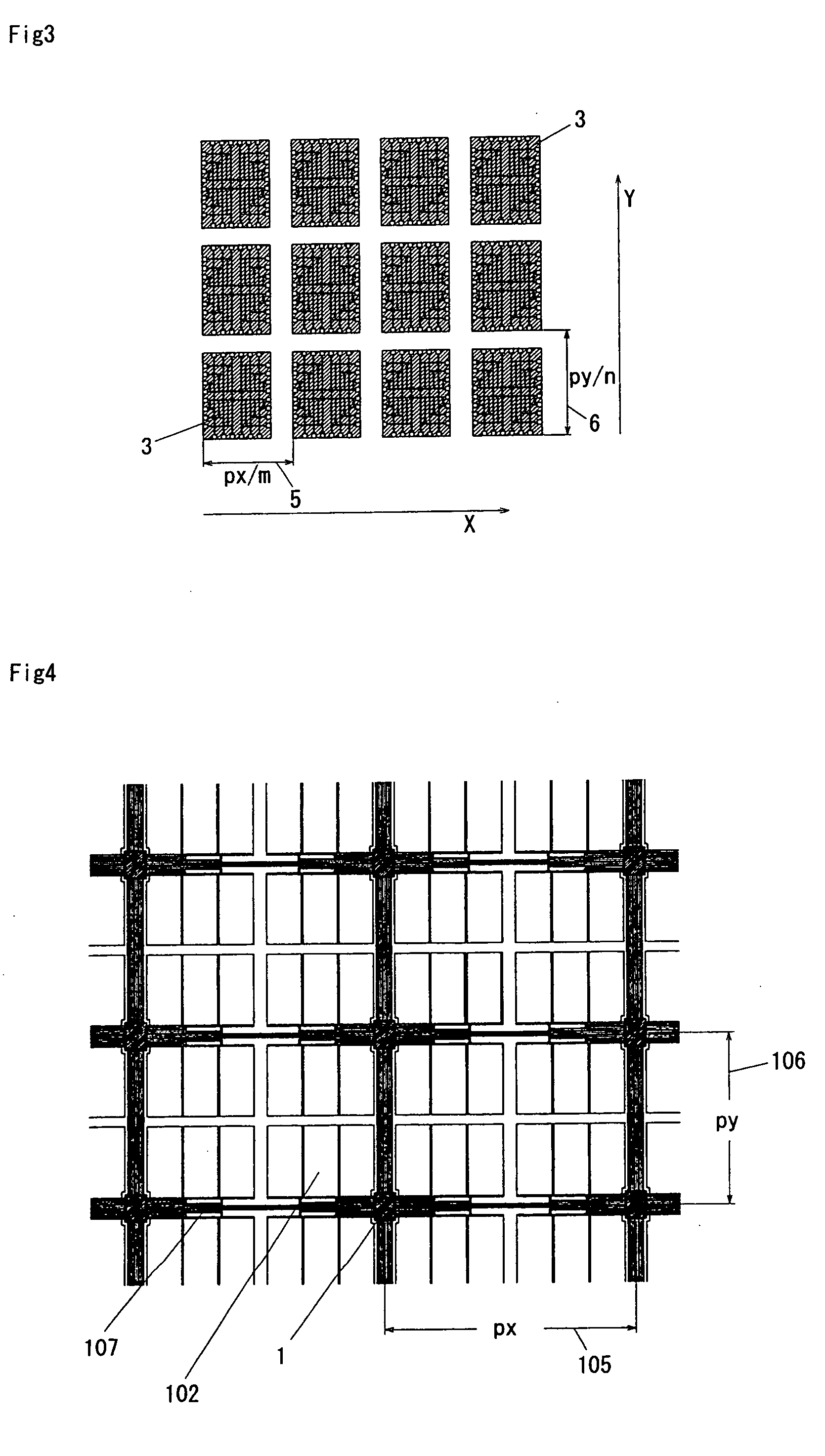
[0132] An actual example will be described, in which the mounting apparatus 300 is used to selectively transfer pixel control devices 1 onto a planar display substrate 100 for a liquid crystal display. The liquid crystal display has a diagonal dimension of 50 inches and a screen resolution of SXGA. When producing pixel control devices 1 having a longitudinal size of 200 μm, a lateral size of 150 μm and a thickness of 0.06 mm at a pitch 5 of 0.215 mm in the first direction X and a pitch 6 of 0.244 mm in the second direction Y on a 8-inch silicon substrate 2 (200 mm in diameter), 370,000 pixel control devices 1 per silicon substrate (having a device formation portion of 140 mm×140 mm) can be produced. When a liquid crystal display 200 having a diagonal dimension of 50 inches (1107 mm×623 mm) and a screen resolution of SXGA (1280×1024×3 colors) is to be produced, one pixel (3 colors) measures 0.86 mm×0.61 mm. That is to say, the pitch 105 of the pixel control devices 1 on the planar di...


PUM


Abstract

There is provided a method for selectively transferring pixel control devices onto a planar display substrate, which method enables prepared pixel control devices to be easily, reliably and inexpensively mounted without inducing any loss of pixel control devices. The pixel control devices (1) are formed in a large number at pitches (5, 6) obtained respectively by dividing pitches (105, 106) on the planar display substrate (100) by natural numbers. The pixel control devices corresponding to the number of the pitches (105, 106) on the planar display substrate (100) are picked up, retained on a transparent thermoplastic resin film (101) formed on the planar display substrate (100) utilizing the plastic deformation of the film and fixed at the peripheries thereof with a transparent ultraviolet curing resin film (104).

Description

TECHNICAL FIELD [0001] The present invention relates to a method for selectively transferring a pixel control device from the substrate of a planar display, such as liquid crystal displays, organic EL displays, etc., on which a plurality of pixel control devices, such as thin film transistors etc., have preliminarily been formed; to a wiring formation method performed after the transfer of the pixel control device; to a pixel control device mounting apparatus used in the pixel control device selection transfer method; and to a planar display substrate. It particularly relates to a pixel control device selection transfer method used when the pixel control device is the one that controls a plurality of pixels; to a pixel control device mounting apparatus used in the method; to a wiring formation method performed after the transfer of the pixel control device; and to a planar display substrate. BACKGROUND ART [0002] In the displays represented by liquid crystal displays and organic EL ...

Claims


Application Information

Patent Timeline
IPC IPC(8): G02F1/13G02F1/1362H01L27/12H01L27/146H01L27/32H01L51/52H01L51/56
CPCG02F1/1362H01L27/12H01L27/14603H01L51/56H01L27/3276H01L51/5281H01L27/3255H10K59/129H10K59/131H10K50/86H10K71/00G02F1/136G09F9/30
Inventor MATSUMURA, HIDEKIKIDA, KENICHIROMINAMI, SHIGEHIRA
Owner MATSUMURA HIDEKI
Why Eureka
Try Eureka