

Polymer micro-ring resonator device and fabrication method
- Summary
- Abstract
- Description
- Claims
- Application Information
AI Technical Summary
Benefits of technology
Problems solved by technology
Method used
Image

Examples
Embodiment Construction
[0024] The following description of the preferred embodiments is merely exemplary in nature and is in no way intended to limit the invention, its application, or uses.
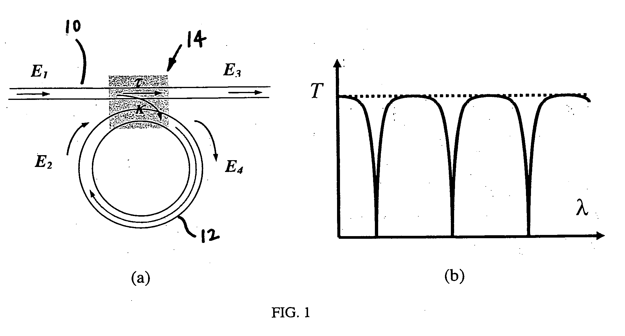
[0025] By way of background, it is believed that a brief discussion of the principles of micro-ring resonators is useful. With particular reference to FIG. 1(a), a waveguide 10 is illustrated coupled with a micro-ring 12. An input (E1), an output (E3), and circulating field inside micro-ring 12 (E2 and E4) can be described by the following coupled-mode equations:
E3=αi(τE1+jκE2)
E4=αi(jκE1+τE2) (1)
where τ and κ is the amplitude transmission and coupling coefficient, respectively, and αi is the insertion loss due to waveguide 10 mode mismatch in coupling region 14. By introducing a single-pass amplitude attenuation factor a, it is appropriate to state E2=aejφE4, where φ is the single-pass phase experienced by light traveling inside micro-ring 12, which is equal to 2πneffL / λ. Here, neff is the effective refractive in...
PUM
 Abstract
Description
Claims
Application Information