
Thin-walled bearing component, produced without material-removing machining

a technology of thin-walled bearings and machining, which is applied in the direction of couplings, heat treatment devices, furnaces, etc., can solve the problem that the cold-rolled strip is unlikely to corrode, and achieve the effect of high-beneficial effect on the dimensional stability of the components

Inactive Publication Date: 2006-04-06
INA SCHAEFFLER KG
View PDF3 Cites 14 Cited by
  • Summary
  • Abstract
  • Description
  • Claims
  • Application Information

AI Technical Summary

Benefits of technology

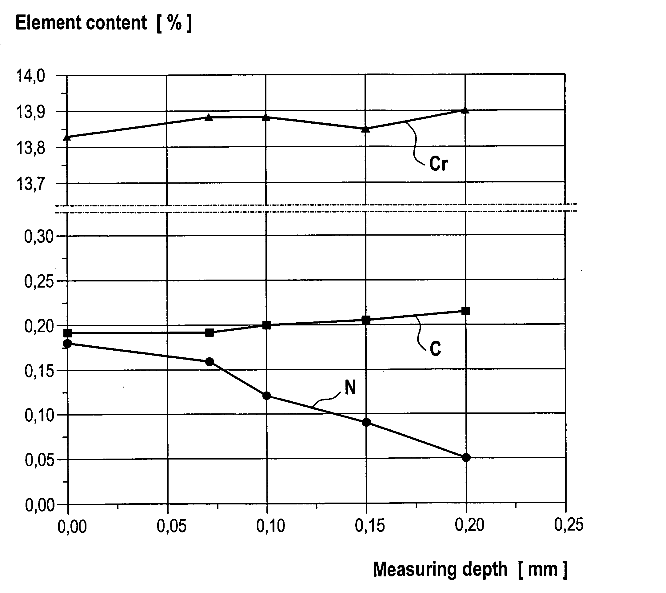
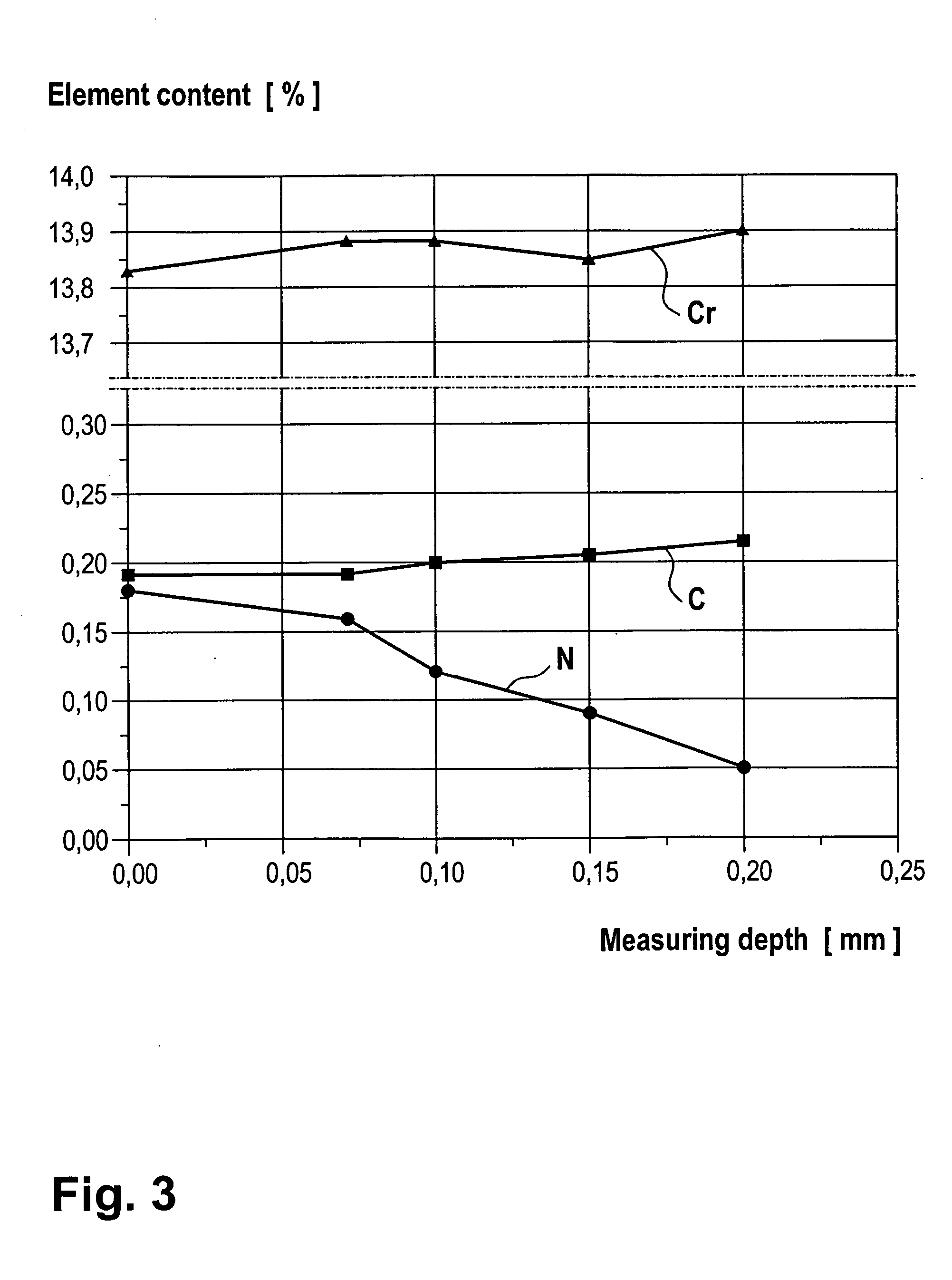
[0010] The introduction of the nitrogen in dissolved form first has the advantage of allowing surface hardening, achieving values of at least 58 HRC or 650 HV. This surface hardness is more than sufficient with respect to the mechanical properties required. However, the nitrogen which is introduced also improves the corrosion resistance of the bearing component to an even greater extent than that which has already been achieved by the high chromium alloying content. It is possible to achieve a corrosion resistance of at least 96 h in the salt spray test in accordance with ASTM B117.
[0013] With a view to maximizing nitrogen solubility in the austenite, it is expedient if the cold-rolled strip is nickel-free. The absence of nickel is also advantageous in that it is also possible to use the bearing component in the food industry sector. The high resistance to water and cleaning agents required there is achieved by the component according to the invention. If possible, there should also be no silicon, since this element reduces the nitrogen solubility. An excessive carbon content is also disadvantageous in this respect. Furthermore, the vanadium, niobium and titanium contents should be relatively low, since these elements increase the risk of precipitation of grain boundary nitrides, which lead to embrittlement.
[0018] This has a highly beneficial effect on the dimensional stability of the components. Consequently, there is no need for sudden quenching, which in the prior art at times leads to changes in dimensions and shape.

Problems solved by technology

The high chromium content means that the cold-rolled strip is unlikely to corrode.

Method used


Image

  • Thin-walled bearing component, produced without material-removing machining
  • Thin-walled bearing component, produced without material-removing machining
  • Thin-walled bearing component, produced without material-removing machining

Examples


Embodiment Construction

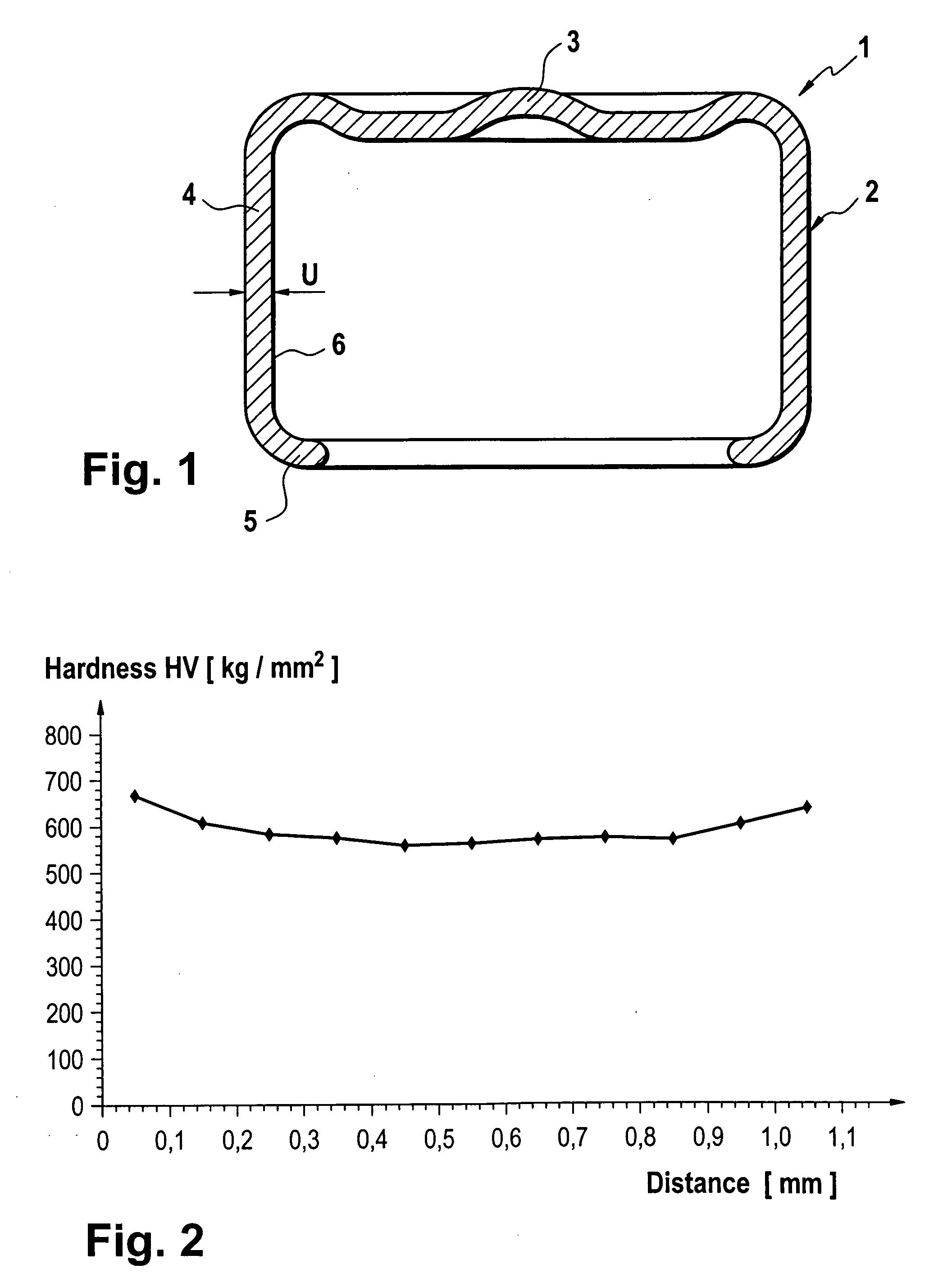
[0025]FIG. 1 shows a sectional view through a bearing component 1 according to the invention in the exemplary form of a universal joint bush 2. This is a rotationally symmetrical component comprising a bush base 3, a bush wall 4 and a flange 5. The universal joint bush is initially deep-drawn from a cold-rolled strip, without the flanged edge 5 yet being provided. This means that the cylinder wall 4 extends in a straight line. After the introduction of needle bearing bodies, the free edge is bent over to form the flanged edge, by means of which the needles are then held in place.

[0026] The universal joint bush 2 is drawn from a cold-rolled strip which has a carbon content of 0.15-0.25% with a chromium alloying content of at least 12%. Known cold-rolled strips which can be used and have these contents as well as isotropic deformation properties, which ensure a homogeneous wall thickness in the drawn component, include, for example, X20Cr13 or X22Cr13. Both are high-alloy steels with...


PUM

PropertyMeasurementUnit
temperatureaaaaaaaaaa
pressureaaaaaaaaaa
elongation at breakaaaaaaaaaa

Abstract

A thin-walled stainless bearing component, in particular a rolling bearing component, such as bearing ring, sleeve or bush, produced without material-removing machining by being deep-drawn from a cold-rolled strip with a carbon content of 0.15-0.25% and a chromium alloying content of at least 12%, and having a martensitic microstructure which is enriched with dissolved nitrogen at least at a side edge zone.

Description

FIELD OF THE INVENTION [0001] The invention relates to a thin-walled preferably stainless, bearing component, in particular a rolling bearing component, such as a bearing ring, sleeve or bush, that is produced without material-removing machining. BACKGROUND OF THE INVENTION [0002] Bearing components of this type, which are used, for example, in needle bearings or the like, are usually deep-drawn from a cold-rolled strip. A precondition for the use of a deep-drawing process is that internal and external diameters of constant wall thickness with a correspondingly low level of roughening of the running surfaces, and which require no further remachining, be achieved. This requires a uniform, isotropic deformability of the cold-rolled strip. In the prior art, for example, a cold-rolled strip of deep-drawing steel containing approximately 0.10% of carbon as well as manganese, chromium and nickel is used for this purpose. Typical steels in this respect are DC04 modified, C15 modified, SAE1...

Claims


Application Information

Patent Timeline
Patent Type & Authority Applications(United States)
IPC IPC(8): C23C8/26
CPCB21D53/10C21D1/06C21D6/002C21D9/40C21D2211/008C22C38/001C22C38/18C23C8/26C23C8/80F16C21/005F16C33/30F16C33/62F16C33/64F16D3/385F16C33/588F16C2361/41Y02T10/86
Inventor GRELL, KARL-LUDWIGKRUPPA, MARTINMULLER, THOMASHARING, WOLFGANGMERKLEIN, CARSTEN
Owner INA SCHAEFFLER KG
Learn More