Liquid feed fuel cell with nested sealing configuration

a fuel cell and liquid feed technology, applied in the field of electrochemical fuel cells, can solve the problems of increasing the size, weight, complexity and cost of hydrogen/oxygen fuel cell systems, and the least density of all possible fuels, and achieve the effect of facilitating fluid diffusion

Inactive Publication Date: 2006-04-13
TEKION
View PDF24 Cites 23 Cited by
  • Summary
  • Abstract
  • Description
  • Claims
  • Application Information

AI Technical Summary

Benefits of technology

[0020] Two or more direct liquid feed fuel cells can be arranged along with a frame to create a fuel cell array. The frame, which can be constructed from a rigid polymeric material such as polycarbonate, has two edge portions, each portion containing a channel. Each channel can accommodate the extending edge portions of at least one direct liquid feed fuel cell. In this configuration, the frame and the two (or more) fuel cells create a reservoir in which the liquid fuel is stored. An adhesive can be used in the frame channels to assist in sealing the liquid fuel inside the array. The frame can have a passage from the inside the array to outside the array to facilitate fluid diffusion at the anode current collectors.

Problems solved by technology

Although the use of hydrogen gas has many favorable properties for fuel cells (such as, for example, the production of pure water as the only reaction product), hydrogen gas is also the least dense of all possible fuels, and is also combustible.
Because of its low density and combustibility, hydrogen gas is difficult and expensive to store and transport.
Although in significantly accumulated quantities CO2 can be detrimental to the earth's climate, it is benign in relation to fuel cell components when included in a reformate stream fed to a fuel cell.
The use of organic fuels as the feed stock for hydrogen / oxygen fuel cells thus increases the size, weight, complexity and cost of hydrogen / oxygen fuel cell systems.
The presence of multiple cells in an electric power generation system puts increased constraints on fuel cell developers to reduce size, weight and cost of individual fuel cells.
However, to date, direct methanol fuel cell (DMFC) developers have been unable to demonstrate a low cost cell that operates efficiently.
To date, solutions for overcoming the problem of methanol crossover are prohibitively expensive.
Other cost-prohibitive solutions include the use of pumps, sensors, filters and water management systems.
First and foremost, formic acid is itself an acid, and can cause skin and eye irritations.
As previously discussed in connection with DMFCs, once the fuel migrates across the membrane to the cathode portion of the fuel cell, a host of problems arise, including loss of fuel for the anodic reaction, contamination of the cathode, and the need to remove fuel from the cathode.
Some prior techniques include the use of bulky and expensive hardware such as screws, bolts, and fasteners.
Other techniques require complicated pressing techniques at high temperatures under highly controlled conditions.
Yet another drawback of previously available assemblies is that the designs impose compressive forces on the sealing components which can cause these components to physically deteriorate and sometimes tear.

Method used


Image

  • Liquid feed fuel cell with nested sealing configuration
  • Liquid feed fuel cell with nested sealing configuration
  • Liquid feed fuel cell with nested sealing configuration

Examples


Embodiment Construction

)

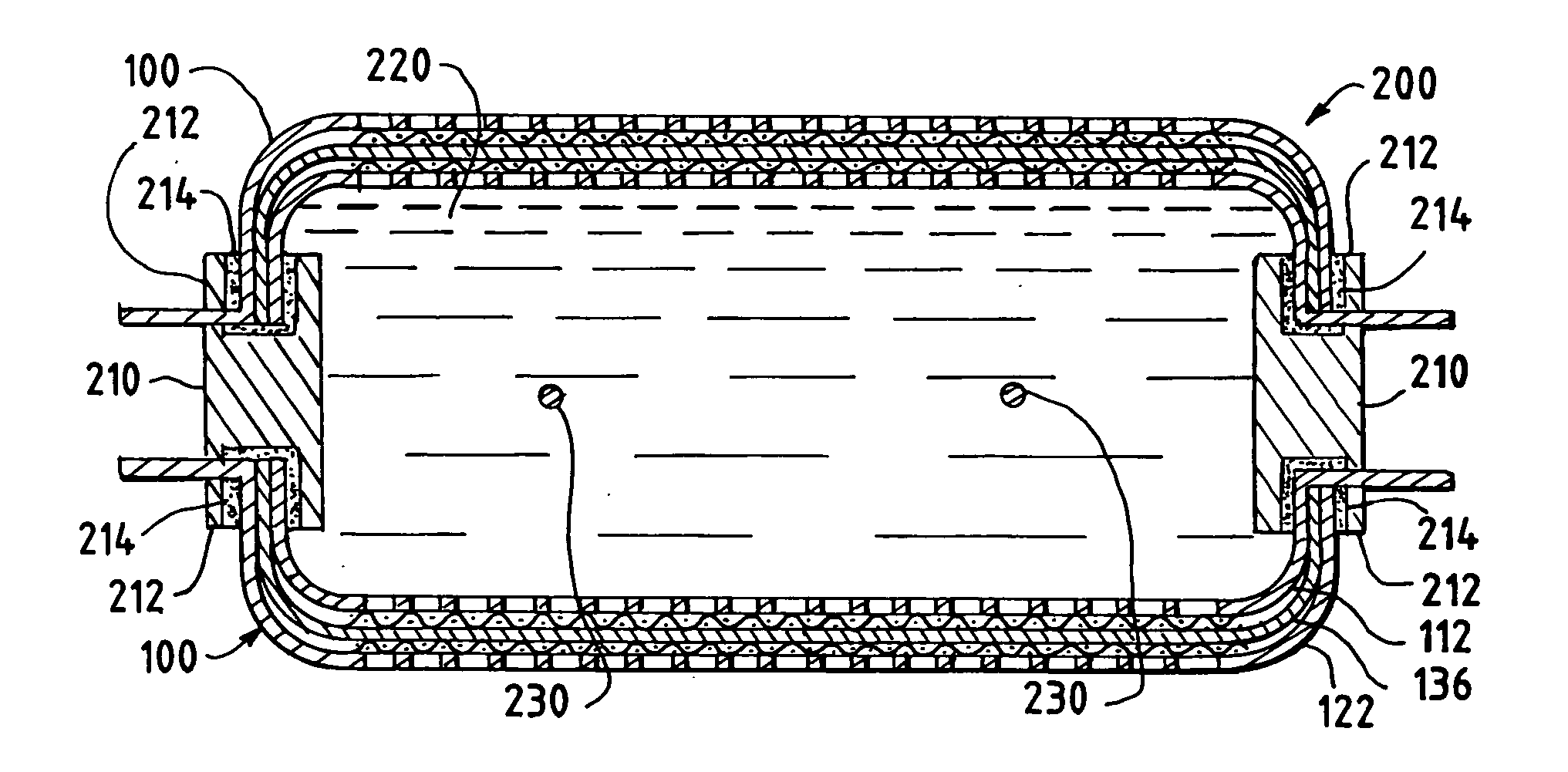
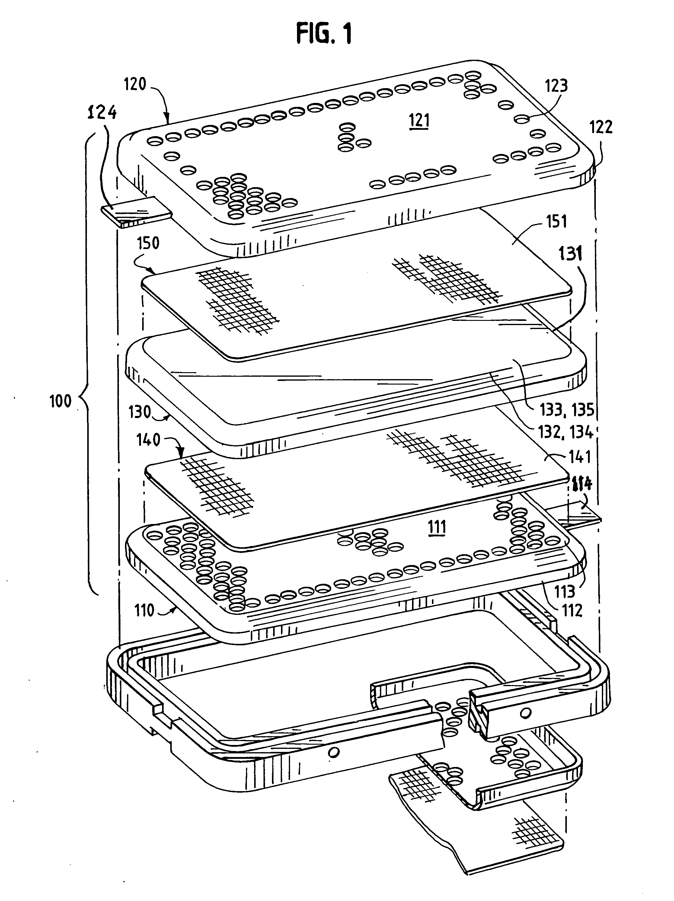
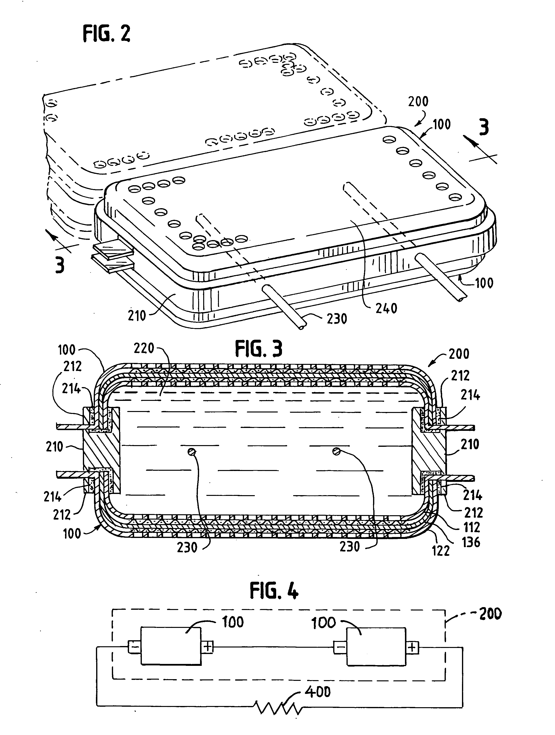
[0027] Turning first to FIG. 1, a single direct liquid feed fuel cell 100 includes an anode current collector 110 cathode current collector 120. The anode current collector 110 is electrically conductive, and has a major planar portion 111 and an edge 112 that extends substantially perpendicularly from and substantially circumscribes the anode current collector major planar portion 111. Extending from the anode current collector edge 112 is an anode current collector electrical connection tab 114. The anode current collector electrical connection tab 114 facilitates connection of the fuel cell 100 in an electrical circuit as illustrated, by example, in FIG. 4. Of course, the anode current collector electrical connection tab 114 can be oriented so as to touch other parts of the anode current collector 110 because of the anode current collector's electrically conductive properties. The anode current collector major planar portion 111 has openings 113 formed therein that facilitate fl...


PUM

PropertyMeasurementUnit
voltageaaaaaaaaaa
electrically conductiveaaaaaaaaaa
volumeaaaaaaaaaa

Abstract

A direct formic acid fuel cell includes a cathode current collector having a perpendicularly extending edge that is capable of cooperating with the perpendicularly extending edge of an anode current collector to effect a press fit. The configuration seals fluids disposed within the volume formed between the current collectors.

Description

FIELD OF THE INVENTION [0001] The present invention relates to electrochemical fuel cells. In particular, the present invention relates to a liquid feed fuel cell in which the current collectors have a nested configuration for sealing fluid reactants within the fuel cell. BACKGROUND OF THE INVENTION [0002] Electrochemical fuel cells convert fuel and oxidant to electricity and reaction product. Solid polymer electrochemical fuel cells generally employ a membrane electrode assembly (“MEA”), which comprises an ion exchange membrane or solid polymer electrolyte disposed between two fluid diffusion layers (FDL). The FDLs can be formed from a variety of electrically conducting materials, such as carbon cloth, carbon paper, metal mesh, or expanded metal foil. The MEA contains a layer of catalyst, typically in the form of finely comminuted precious metal(s) at each membrane / FDL interface to form the electrodes that induce the desired electrochemical reaction. The electrodes are electrically...

Claims


Application Information

Patent Timeline
Patent Type & Authority Applications(United States)
IPC IPC(8): H01M4/86H01M8/10H01M2/08
CPCH01M4/661H01M4/667H01M8/0232H01M8/0234H01M8/0245H01M8/0271H01M8/0276H01M8/0284H01M8/1009H01M8/1011H01M8/22H01M12/04H01M12/065Y02E60/521Y02E60/10Y02E60/50H01M8/0273H01M8/241
Inventor MASEL, RICHARD I.MOZSGAI, GREGORY
Owner TEKION
Why Eureka
Try Eureka