Hydrogen storage container and mixture therein

a technology of hydrogen storage containers and hydrogen storage mixtures, which is applied in the directions of transportation and packaging, separation processes, and packaged goods types, etc., can solve the problems of difficult heat transfer into/out of hydride beds, poor conductivity of hydrogen storage alloys, and the hydrogen-absorbing method, so as to increase the thermal conductivity of solid beds and large surface area , good thermal conductivity

Inactive Publication Date: 2006-04-20
ZHEJIANG UNIV +1
View PDF0 Cites 18 Cited by
  • Summary
  • Abstract
  • Description
  • Claims
  • Application Information

AI Technical Summary

Benefits of technology

[0021] 1) It is a mixture of hydrogen storage alloy granules and non-hydrogen-absorbing metal and / or alloy fibers that is loaded into a hydrogen storage container. The fibers in the mixture have sufficiently large surface area and form a three dimensional network structure, which is able to prevent the free and relatively long distance movement and local accumulation of hydrogen storage granules in certain regions of the container.
[0022] 2) Because the aforesaid non-hydrogen-absorbing metal and / or alloy fibers have a good thermal conductivity, the addition of the non-hydrogen-absorbing fibers into the hydrogen storage container effectively increases the thermal conductivity of the solid bed inside the container. Because the content of the fibers in the mixture is below 10%, sometimes only 1%, its effect on the reduction of the hydrogen storage capacity of the mixture is small.
[0023] 3) The hydrogen storage alloy granules in this hydrogen storage container do not need any previous treatment, such as copper plating, compaction, doping, sintering or repeated hydriding / dehydriding cycling. There is no need to add any organic solvent into the containers. Due to the above reasons, the hydrogen storage containers of the present invention are of low cost, highly efficient, and are able to be operated safely for a long period of time.
[0024] 4) This hydrogen storage container is easy to manufacture and has high operation efficiency. This kind of hydrogen storage containers can be used for both stationary hydrogen storage and mobile or even portable hydrogen storage including the fuel tanks for hydrogen fuel cells or for internal combustion vehicles.

Problems solved by technology

However, there are several problems with the hydrogen-absorbing method.
On one hand, as the heat conductivity of hydrogen storage alloys is intrinsically rather poor, being equivalent to that of broken glass or sand, it is rather difficult to make heat transfer into / out of a hydride bed.
Because of the poor heat transfer, the temperature of a hydride hydrogen container usually increases rapidly during the hydrogen absorbing process and drops rapidly during the hydrogen desorbing process.
The particles settle down and compact into rather solid masses in certain localities of the container, where the volume expansion of the alloy during hydriding generally causes local deformation or even breakage of the container.
Therefore, the key technical problems to be solved include the increase of the thermal conductivity of the hydride bed and the prevention of the free movement of hydrogen storage granules inside the container during the hydrogen charging / discharging processes.
The trial was a failure because no adequate room was provided in the pellets for the expansion of the hydrogen storage alloy granules, which decrepitate during hydriding.
However, the process, as stated above, is complicated.
In addition, the doping and sintering treatments may lower hydrogen storage capacity by about 15%.
The drawbacks for this process were also the high cost due to the initial hydriding / dehydriding, copper-plating and hydrostatic compression and vacuum sintering processes.
The service life of the container of this design was reported to be very long.
However, the initial cost of the containers of this design was the highest due to the costs of materials, precision machining and assembly.

Method used


Image

  • Hydrogen storage container and mixture therein
  • Hydrogen storage container and mixture therein
  • Hydrogen storage container and mixture therein

Examples


example 1

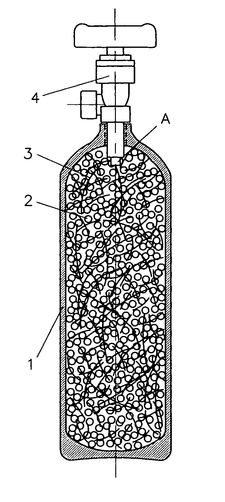
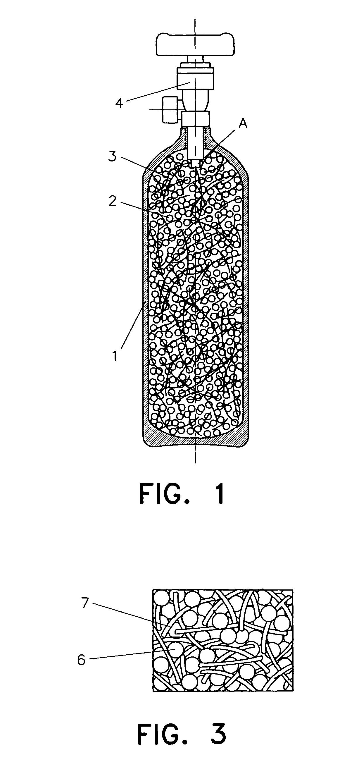
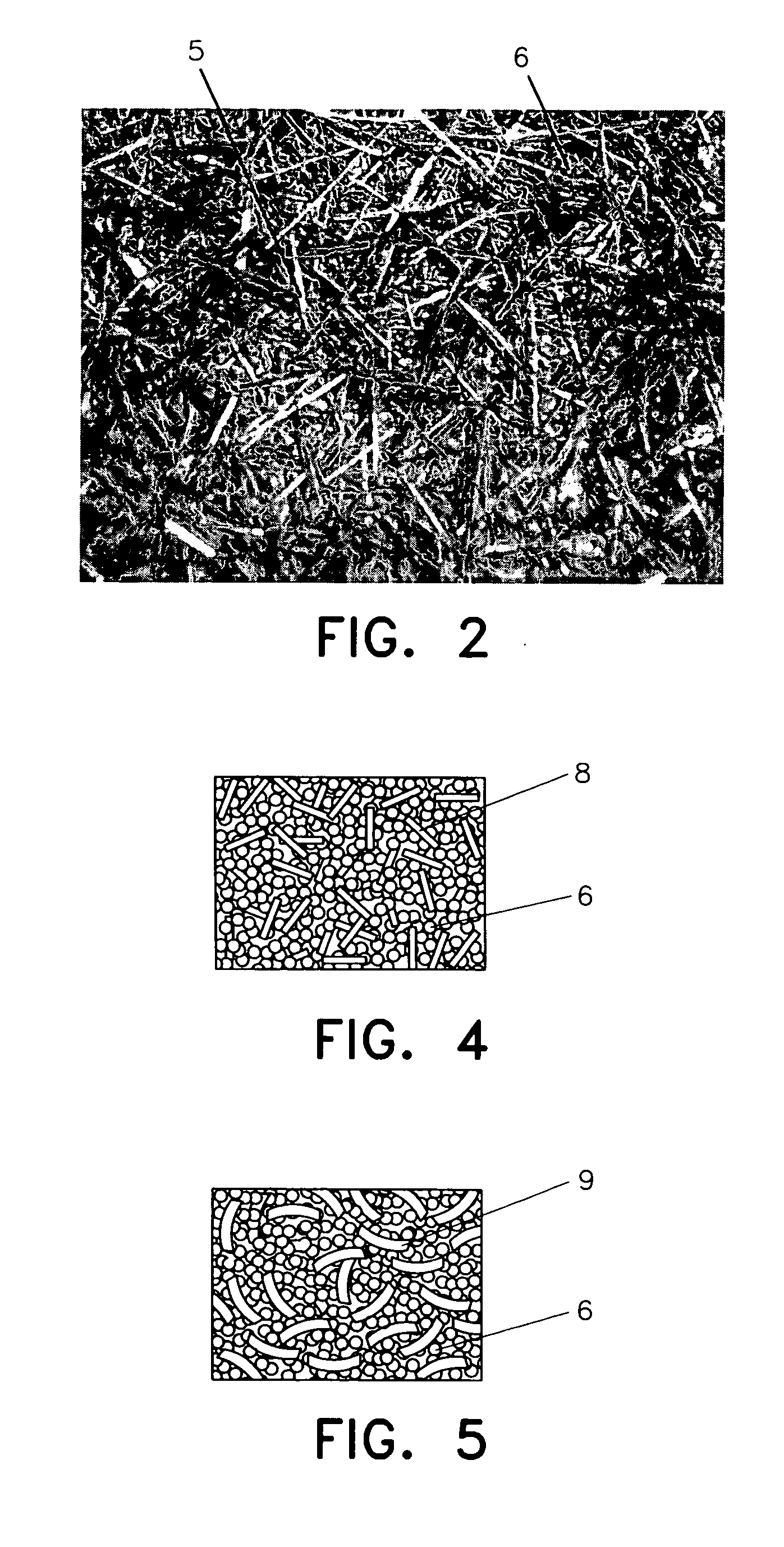
[0040] A hydrogen storage container consists of a container casing, a hydrogen storage mixture and a valve. The hydrogen storage mixture loaded into the container is made of hydrogen storage alloy granules and non-hydrogen-absorbing aluminum fibers. Hydrogen storage alloy MmNi4.5Mn0.5 used in this example belongs to the rare-earth based hydrogen storage alloys; Mm stands for the cerium-rich mischmetal. The ingots of MmNi4.5Mn0.5 should be crushed into small granules with a diameter of about 3 mm before being loaded into the container. The average length of the aluminum fibers is about 3 mm and average cross section is about 0.5 square millimeters. The total weight of aluminum fibers is about one percent of the total weight of hydrogen storage alloy granules. The bulk specific weight of the mixture is 3.6 g·cm−3. The operation of the hydrogen storage container is as follows. At first, the pressure in the container is adjusted to 133 Pa. Then, hydrogen of 99.99% purity is filled into ...

example 2

[0042] The hydrogen storage alloy for the granules in the mixture is the titanium-based alloy TiFe0.85Mn0.15. The non-hydrogen-absorbing alloy fibers are made of brass, with an average length of 11 mm and average cross section 1.2 mm2. The weight ratio of brass fibers to hydrogen storage alloy granules is about 0.05. The bulk specific weight of the mixture is 3.0 g·cm−3. The process of activation and initial charging is similar to those of Example 1. The test results show that the hydrogen storage capacity is 1.7%. Neither damage nor deformation of the container have been detected after 1000 hydriding / dehydriding cycles.

example 3

[0043] Magnesium based alloy Mg2Ni is used for the hydrogen storage alloy in the mixture of this example. The non-hydrogen-absorbing alloy for making alloy fibers is nickel alloy. The average length of the nickel alloy fibers is 20 mm, and their average cross sectional area is 2 mm2. The weight ratio of the nickel alloy fibers to the hydrogen storage magnesium based alloy is about 0.1. The size of hydrogen storage alloy granules initially loaded into the containers should be under 5 mm in diameter. The bulk density of the mixture is 2.2 g·cm−3. In this example, pre-heating of the container is necessary for hydrogen absorbing and desorbing. The container is heated to 300° C. and the pressure is adjusted to 50 Pa before the initial charging of hydrogen. Then, the container is charged with hydrogen of 99.99% purity at a pressure of 3.0 MPa. Then, the activation and hydriding of Mg2Ni can be started. During hydriding, Mg2Ni transforms to Mg2NiH4. The test results show that the hydrogen ...


PUM

PropertyMeasurementUnit
lengthaaaaaaaaaa
temperatureaaaaaaaaaa
thermal conductivityaaaaaaaaaa

Abstract

This invention relates to a new kind of hydrogen storage mixture and container thereof. This hydrogen storage container consists of a container casing, a hydrogen storage mixture and a valve. The hydrogen storage mixture loaded inside the container is made of hydrogen storage alloy granules and metal fibers and/or non-hydrogen-absorbing alloy fibers that do not absorb hydrogen. The non-hydrogen-absorbing fibers are dispersed among the hydrogen storage alloy granules and form a network structure. The non-hydrogen-absorbing fibers include non-hydrogen-absorbing metal fibers and/or non-hydrogen-absorbing alloy fibers, or their mixture. In the hydrogen storage mixture, the weight ratio of the non-hydrogen-absorbing fibers to the hydrogen storage alloys is about 0.01˜0.1. The hydrogen storage installation adopting the technology of this invention can effectively prevent the metal hydride granules from moving over a comparatively long distance and accumulating in some locations in the container during hydriding and dehydriding, and also can improve the thermal conductivity of the hydrogen storage mixture inside the container. The hydrogen storage container of this invention is easy to manufacture, safe to use, and low in cost. This invention can be used for the manufacture of hydrogen storage containers for hydrogen storage, transport, compression and purification.

Description

FIELD OF THE INVENTION [0001] The present invention relates to hydrogen storage, transport and compression technology, more specifically, to a hydrogen storage equipment and a related hydrogen storage mixture. DESCRIPTION OF THE RELATED ART [0002] Hydrogen is an important industrial raw material. It is also an ideal clean fuel and a secondary energy source for the future. Presently, there are three main methods for storing and transporting hydrogen, namely high-pressure containers (steel or aluminum alloy tanks), liquid hydrogen containers (low temperature Dewar flasks) and metal hydride hydrogen storage containers. The most distinct advantages for using metal hydride hydrogen storage containers to store and transport hydrogen are its higher level of storage and transport safety, and the higher volume hydrogen storage density (the mass of hydrogen stored in a definite container volume) than storage in a high pressure container or in a liquid hydrogen storage container of the same vo...

Claims


Application Information

Patent Timeline
Patent Type & Authority Applications(United States)
IPC IPC(8): B65B3/00B01D53/04F17C1/00F17C11/00
CPCB01D53/02B01D53/0415B01D2253/1126B01D2257/108B01D2258/01B01D2258/0208B01D2259/4143B01D2259/4525B01D2259/4541B01D2259/4566F17C11/005Y02E60/321Y02E60/32
Inventor CHEN, CHANGPINCHEN, LIXINWANG, QIDONG
Owner ZHEJIANG UNIV
Why Eureka
Try Eureka