Vacuum sealed surface acoustic wave pressure sensor

a surface acoustic wave and pressure sensor technology, applied in the direction of fluid pressure measurement, fluid pressure measurement by electric/magnetic elements, instruments, etc., can solve the problems of supplementary and uncontrollable stress, inaccurate drilling of quartz substrate and alignment of two plates, and time-consuming drilling of quartz plates, etc., to reduce the time devoted to drilling.

Inactive Publication Date: 2006-04-27
HONEYWELL INT INC
View PDF21 Cites 31 Cited by
  • Summary
  • Abstract
  • Description
  • Claims
  • Application Information

AI Technical Summary

Benefits of technology

[0015] It is, therefore, one aspect of the present invention to provide for an improved surface acoustic wave (SAW) sensor structure that can be realized on ST quartz.
[0019] It is also an aspect of the present invention to provide for a SAW pressure sensor that can be implemented at a wafer-scale, thereby allowing for a cost reduction per chip thereof.
[0022] Such a method and system for the realization of the diaphragm ensures: (i) a precise alignment of the sensor by respect to the diaphragm, (ii) a precise control of the thickness of the diaphragm, (iii) a good quality (roughness) for the realized diaphragm, and (iv) a reduced stress induced into the diaphragm due to a best fit between TCEs.
[0024] The two wafers can be aligned one with respect to the other utilizing commercially available double-sided alignment equipment. The direct bonding can be performed utilizing commercial equipment typically utilized in MEMS facilities for carrying out anodic bonding silicon to glass. The system formed by the two bonded wafers can be utilized for thinning the wafer (“base” wafer) that supports the SAW sensor. The thinning can be realized by lapping and chemical mechanical polishing (CMP). The purpose of this supplementary process is to decrease the time devoted to dry etching of the diaphragm.

Problems solved by technology

Another problem observed in the aforementioned configurations arises from the mismatch between the substrate and the quartz temperature coefficient of expansion (TCE) that induces supplementary and uncontrollable stress into diaphragm.
In such a configuration, the stress induced by the mismatch between the TCE can be reduced but, again, the drilling of the quartz substrate and the alignment of the two plates are not accurate.
Moreover, drilling a quartz plate is time consuming and can induce defects into the plate.
Such defects decrease the strength of the material.
Such a method surpasses the previous problems related to stress induces by temperature mismatch and to drilling.
The alignment of the diaphragm, however, remains a problem.
Careful mechanical set-up increases the cost of this sensor.
All such techniques involve some mechanical problems.
A polymer sealing method has also been proposed, but is generally not suitable for pressure sensor applications.

Method used


Image

  • Vacuum sealed surface acoustic wave pressure sensor
  • Vacuum sealed surface acoustic wave pressure sensor
  • Vacuum sealed surface acoustic wave pressure sensor

Examples


Embodiment Construction

[0038] The particular values and configurations discussed in these non-limiting examples can be varied and are cited merely to illustrate at least one embodiment of the present invention and are not intended to limit the scope of the invention.

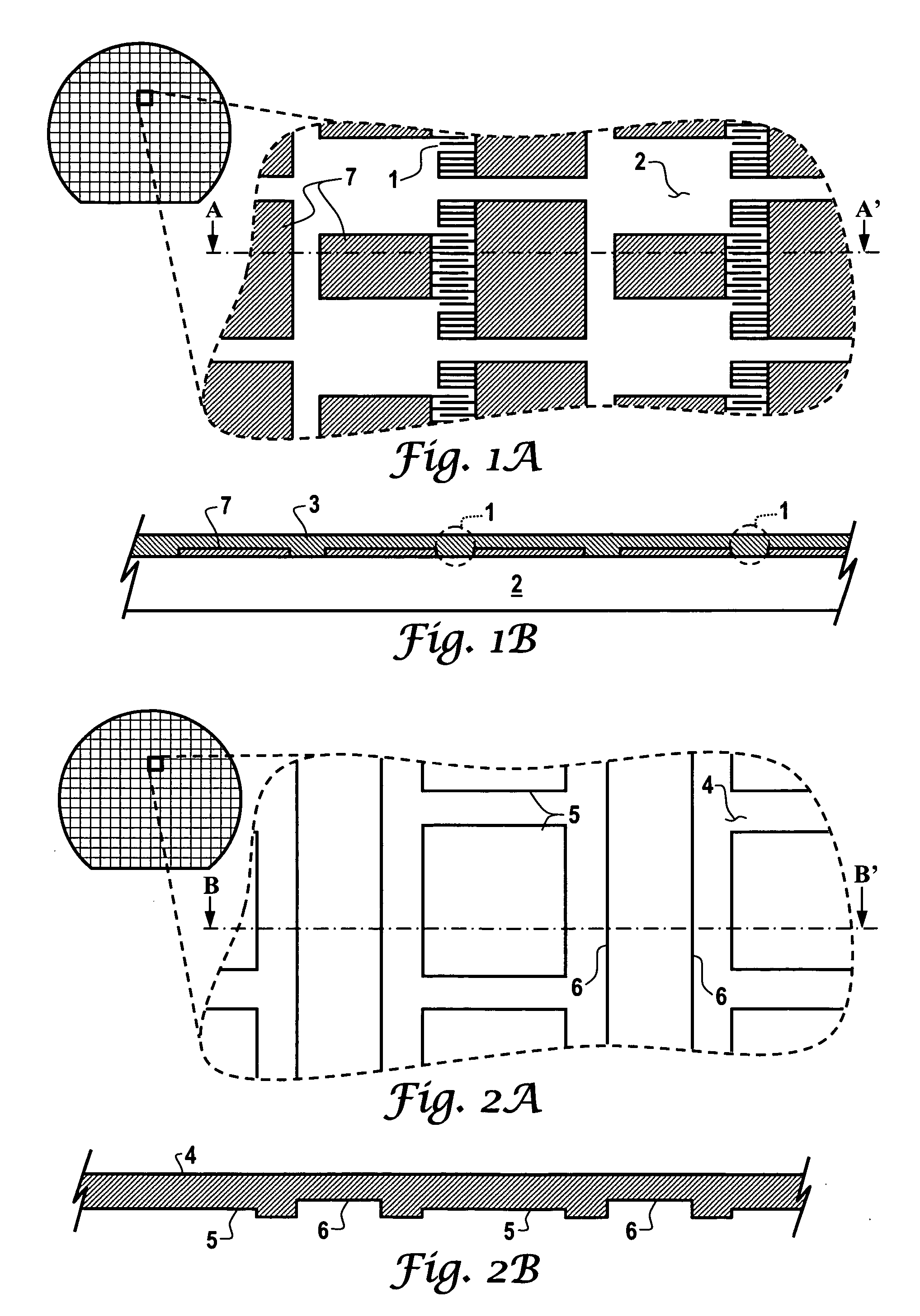
[0039]FIG. 1(a) illustrates an upper view of a part of a wafer supporting a plurality of resonators, in accordance with a preferred embodiment. FIG. 1 (b) illustrates a view of the AA′ cross section from FIG. 1(a), in accordance with a preferred embodiment. Note that in FIGS. 1-8 disclosed and illustrated herein, identical or similar parts are generally indicated by identical reference numerals.

[0040] As depicted in FIG. 1(a), a SAW resonator 1, which functions as a main sensing element, can be realized on a “base” quartz wafer 2. In order to take advantage of surface wave propagation, the material for the quartz “base” can be, for example, ST-cut quartz or another orientation or material suitable for such propagation. The two wafers (“base”...


PUM

PropertyMeasurementUnit
pressureaaaaaaaaaa
mechanicalaaaaaaaaaa
temperatureaaaaaaaaaa

Abstract

A vacuum sealed SAW pressure sensor is disclosed herein, which includes a sensing element configured as a SAW device (e.g., SAW resonator or SAW delay line) supported by a thin diaphragm. The substrate material can be implemented as a quartz wafer (i.e., a “base” wafer). The SAW device can be configured on one side of the wafer and the diaphragm etched on the opposite side. A quartz micromachined pressure sensor can thus be realized, which operates based on a variation of the surface wave velocity of a SAW device situated on the thin diaphragm. The SAW sensor is generally sealed in a vacuum and diaphragm sustains the sensor, thereby implementing a sensor on a wafer scale while allowing for a cost reduction per chip.

Description

TECHNICAL FIELD [0001] Embodiments are generally related to surface acoustic wave sensors. Embodiments are also related to pressure sensors based surface acoustic wave (SAW) technology. Embodiments are additionally related to micro electromechanical systems (MEMS). BACKGROUND OF THE INVENTION [0002] Surface acoustic wave (SAW) devices have been utilized in a number of sensing applications, and have been adapted for use with telecommunications equipment for the realization of delay lines and filters. Filters and delay lines require very good temperature and stress stability. Proper design, material choice (e.g., quartz cuts) and packaging techniques have lead to the realization of devices having improved performances. Note that such “improved performances” are principally related to the stability of surface wave velocities, which must remain as stable as possible within a specified range of temperature and stress. [0003] The modification of the surface wave velocity due to such afore...

Claims


Application Information

Patent Timeline
Patent Type & Authority Applications(United States)
IPC IPC(8): B23P17/04G01R3/00
CPCG01L9/0025Y10T29/49007Y10T29/49H01L2924/181H01L2224/48091H01L2224/48247H01L2924/15151H01L2924/1815H01L2924/00014H01L2924/00012
Inventor AVRAMESCU, VIOREL V.COBIANU, CORNEL P.PAVELESCU, IOAN
Owner HONEYWELL INT INC
Why Eureka
Try Eureka