Rare earth doped single polarization double clad optical fiber with plurality of air holes

a rare earth doped, optical fiber technology, applied in optical fibers with polarisation, glass deposition burners, instruments, etc., can solve the problems of low capability of handling multi-mode optical sources, low thermal stability of plastics for many applications, and easy moisture damage, etc., to reduce splicing loss, reduce overall fiber length, and reduce work and cost

Inactive Publication Date: 2006-04-27
CORNING INC
View PDF14 Cites 27 Cited by
  • Summary
  • Abstract
  • Description
  • Claims
  • Application Information

AI Technical Summary

Benefits of technology

[0031] One advantage of the optical fiber of the present invention is its capability to produce gain, thus being capable for use in a laser or an optical amplifier while (i) performing as single polarization fiber and exhibiting a single polarization band SPB width of greater than 10 nm and even more preferably greater than 15 nm, and (ii) being capable of handling relatively large amounts of optical power. Another advantage of the optical fiber of the present invention is that because it performs both as a gain fiber and the SP fiber, it eliminates the need to for splicing together gain fiber and the single polarization fiber, thereby reducing the splicing loss, the overall fiber length, while eliminating work and cost associated with splicing the two fibers together.

Problems solved by technology

This type of fiber has low capability of handling high power multimode optical sources due to the difficulty of efficiently coupling multimode light from a high power optical (light) source (also referred to herein as optical pump or pump) into the rare-earth doped fiber core.
Such plastic may not have the desired thermal stability for many applications, may delaminate from the first cladding, and may be susceptible to moisture damage.
In addition, this type of double clad optical fiber may be suitable only for sustained use with relatively low power (lower than 20 Watts) optical sources.
When high power sources (more than 100 Watts) are utilized, this type of optical fiber heats and the polymer material of the outer cladding layer carbonizes or burns, resulting in device failure, especially when the fiber is bent.
At medium powers (20 Watts to below 100 Watts), the polymer outer cladding ages relatively quickly, losing its mechanical and optical characteristics and becoming brittle, thus shortening the device life.
The disclosed fiber, however, is not suitable for high power applications because it has a relatively low outer cladding diameter and NA, and therefore, low coupling efficiency due to light leakage outside of the optical fiber.
That is, a relatively large portion of the light does not enter the optical fiber and is lost.
Although this may not be an issue in applications when only a small amount of optical power needs to be coupled into the fiber, such fiber is not efficient for high power applications when the light source power is 100 Watts or more.
However, the noncircular geometry of the core alone is, generally, not sufficient to provide the desired single polarization properties.
Furthermore, these fibers are not optically active fibers and, therefore are not suitable for use as a laser or an amplifier fiber.

Method used


Image

  • Rare earth doped single polarization double clad optical fiber with plurality of air holes
  • Rare earth doped single polarization double clad optical fiber with plurality of air holes
  • Rare earth doped single polarization double clad optical fiber with plurality of air holes

Examples


example 1

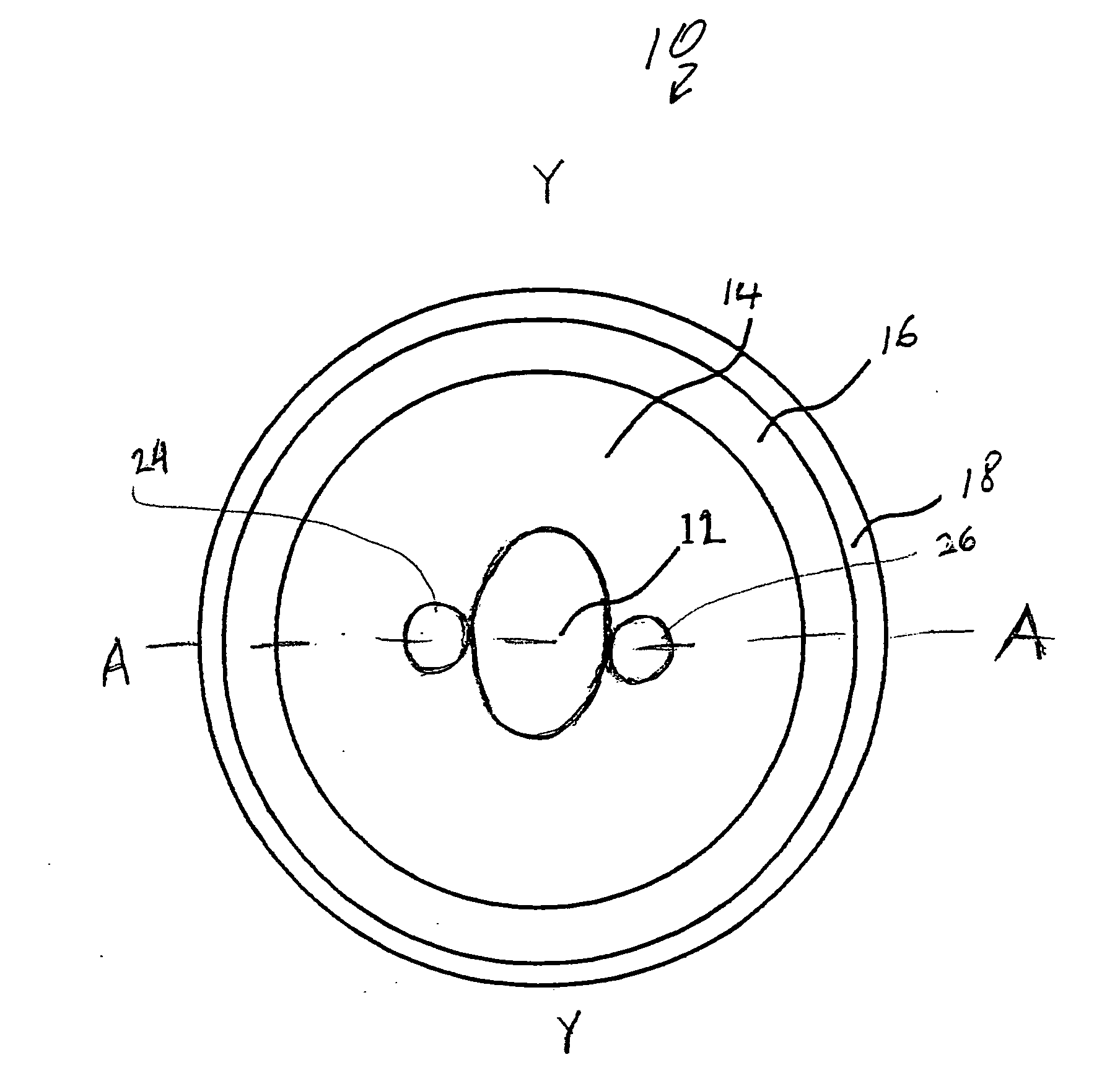
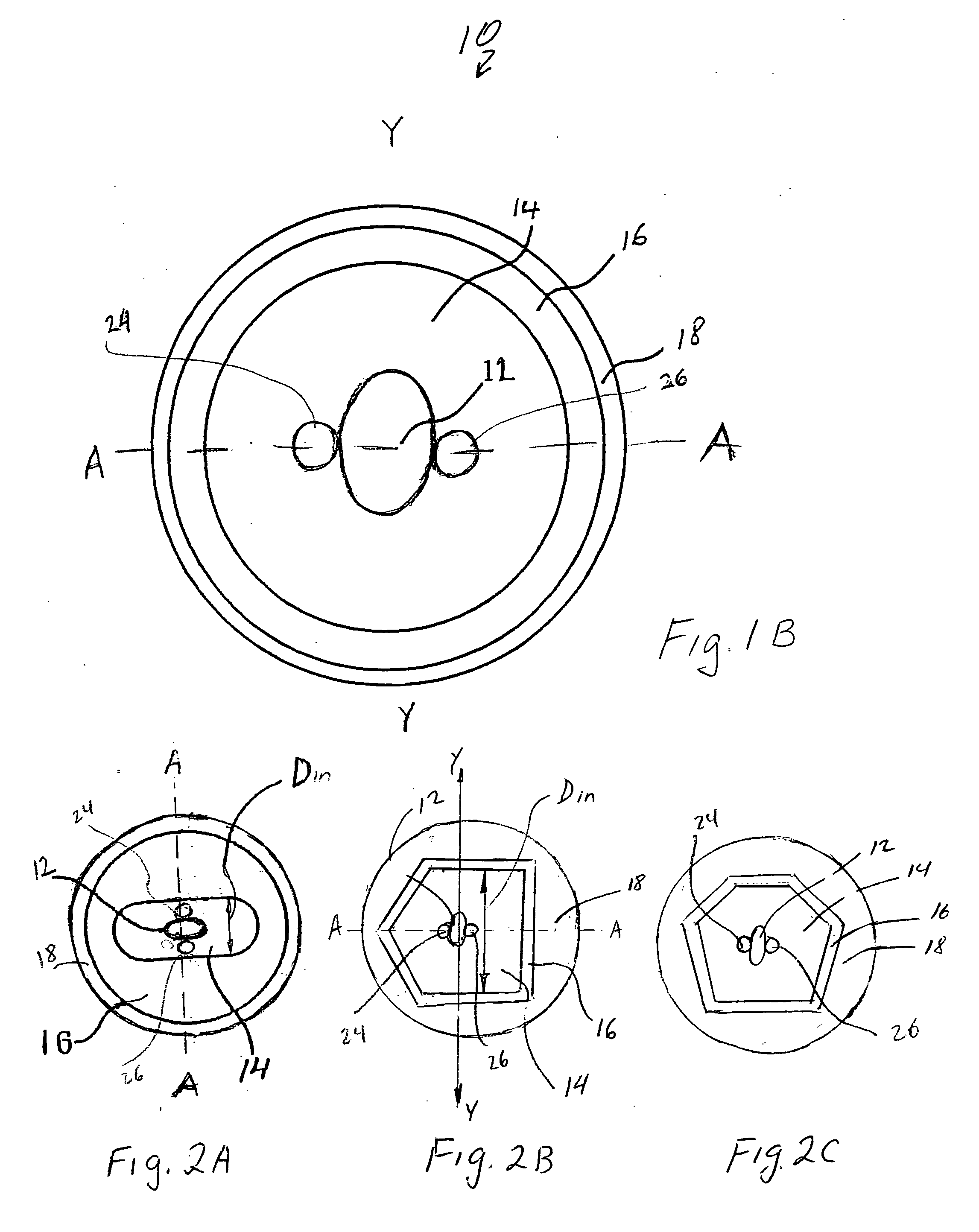
[0076]FIGS. 3A and 3B illustrate schematically a relative refractive index profile of a first exemplary optical fiber of the present invention. More specifically, FIGS. 3A and 3B depicts optical fiber's refractive index percent delta (relative to that of the pure silica) vs. the distance measured from the core center. FIG. 3A illustrates schematically a refractive index profile taken across the region that does not contain the air holes, for example, along the line Y-Y of the fiber depicted in FIG. 1B. FIG. 3B illustrates schematically a refractive index profile of the same fiber, but taken across the region that contains the air hole 24 (for example, along the line A-A of the fiber depicted in FIG. 1B).

[0077]FIG. 3C illustrates measured refractive index profile (percent delta, relative to that of the pure silica) of a first exemplary optical fiber of the present invention along the Y-Y axis, measured from the core center. This optical fiber has the cross-section illustrated in FIG...

example 2

[0085]FIG. 6 illustrates a refractive index profile of a second exemplary optical fiber of the present invention, across the region that does not intersect the airholes 24, 26 (along the axis Y-Y, for example). More specifically, FIG. 6 depicts refractive index delta as vs. the radius for the second exemplary optical fiber. This optical fiber has a Yb doped, silica based core 12 which is multi mode at the lasing wavelength of 1100 μm, a silica based inner cladding 14 having two sections of almost the same index of refraction (delta %≈0) and an outer cladding 16 which is doped with fluorine. The NA of the inner cladding is 0.16. FIG. 6 illustrates that the refractive index difference (delta %) of the core 12 is about 0.7, that the fluorine doped outer cladding 16 has the refractive index delta of about −0.7.

[0086] The double clad optical fiber illustrated in FIG. 6 is also suitable for use in a fiber laser device. FIG. 7 corresponds to the optical fiber of FIG. 6. More specifically,...


PUM

PropertyMeasurementUnit
diameteraaaaaaaaaa
operating wavelength rangeaaaaaaaaaa
output powersaaaaaaaaaa

Abstract

An optical fiber including: (i) a silica based, rare earth doped core having a first index of refraction n1; (ii) a silica based inner cladding surrounding the core and having a second index of refraction n2, such that n1>n2, said inner cladding having a plurality of air holes extending longitudinally through the length of said optical fiber; (iii) a silica based outer cladding surrounding said inner cladding and having a third index of refraction n3, such that n2>n3, wherein said optical fiber supports a single polarization mode within the operating wavelength range.

Description

[0001] Parts of this invention were made with Government support under Agreement No. MDA972-02-3-004 awarded by DARPA. The Government may have certain rights in some of the claims of the invention.BACKGROUND OF THE INVENTION [0002] 1. Field of the Invention [0003] The present invention relates generally to optical waveguide fibers, and more particularly to a rare earth doped optical fiber exhibiting single polarization properties. [0004] 2. Technical Background FIELD OF THE INVENTION [0005] The present invention relates generally to double clad rare earth doped optical fibers, and particularly to all glass rare earth doped optical fibers suitable for use with high power light sources or in optical fiber lasers and optical amplifiers. TECHNICAL BACKGROUND [0006] Optical fiber has become a favorite medium for telecommunications due to its high capacity and immunity to electrical noise. Single clad rare earth doped optical fiber has been widely used in the field of optical amplifiers a...

Claims


Application Information

Patent Timeline
Patent Type & Authority Applications(United States)
IPC IPC(8): G02B6/032
CPCC03B37/01234C03B37/0124C03B37/01413C03B37/01446C03B2201/12C03B2201/14C03B2201/28C03B2201/31C03B2201/36C03B2203/12C03B2203/14C03B2203/23C03B2205/10C03B2207/90G02B6/023G02B6/02338G02B6/02366G02B6/024G02B6/03611G02B6/0365G02B6/03666G02B2006/1208H01S3/06716H01S3/06729H01S3/1618H01S3/1695
Inventor BERKEY, GEORGE E.CHEN, XINKOH, JOOHYUNLI, MING-JUNNOLAN, DANIEL A.WALTON, DONNELL T.WANG, JIZENTENO, LUIS A.
Owner CORNING INC
Why Eureka
Try Eureka