
Electolytic processing apparatus

a processing apparatus and electrolysis technology, applied in the direction of electrical-based machining electrodes, manufacturing tools, electric circuit machining, etc., can solve the problems of processing properties, workpiece surface roughness, and fiber seams that may influence the surface roughness of workpieces, and achieve stable processing performance and flexibility

Inactive Publication Date: 2006-05-04
EBARA CORP
View PDF6 Cites 16 Cited by
  • Summary
  • Abstract
  • Description
  • Claims
  • Application Information

AI Technical Summary

Benefits of technology

[0013] The present invention has been made in view of the above drawbacks. It is, therefore, a first object of the present invention to provide an electrolytic processing apparatus which can achieve stable processing performance and can flexibly cope with small electrodes and various shapes of electrodes.
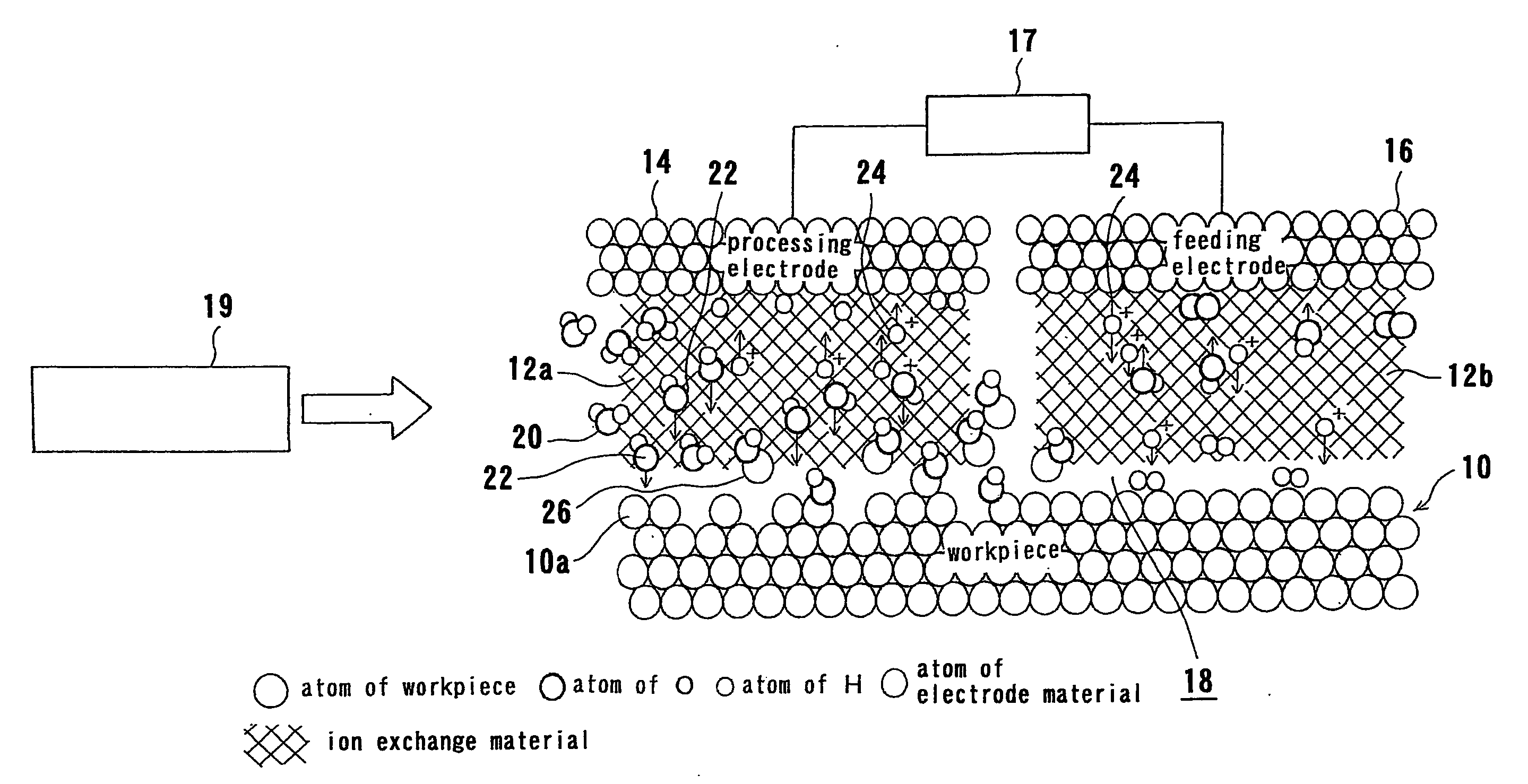
[0017] In the case where liquid such as ultrapure water, which has a large resistivity, is used, it is desirable that the workpiece 10 is brought into contact with or close to the ion exchange material 12a, because it is possible to reduce the electric resistance, the requisite voltage, and hence the power consumption.
[0020] As described above, the electrolytic processing apparatus according to the present invention employs only a dissolution reaction due to an electrochemical interaction and clearly differs in the processing principle from a CMP apparatus, which employs a combination of a physical interaction between a polishing tool and a workpiece and a chemical interaction between a chemical species in a polishing liquid and the workpiece. Therefore, the removal process can be performed without deteriorating the properties of materials. Even if the workpiece is formed by a material having a low mechanical strength, such as the aforementioned low-k material, the removal process can be performed without any physical damage to the workpiece. Further, when a fluid having an electric conductivity of 500 μS / cm or less, preferably pure water, more preferably ultrapure water, is used as a processing liquid instead of an electrolytic solution used in a conventional electrolytic process, it is possible to remarkably reduce contamination of a surface of the workpiece and to easily treat waste liquid after the electrolytic process.
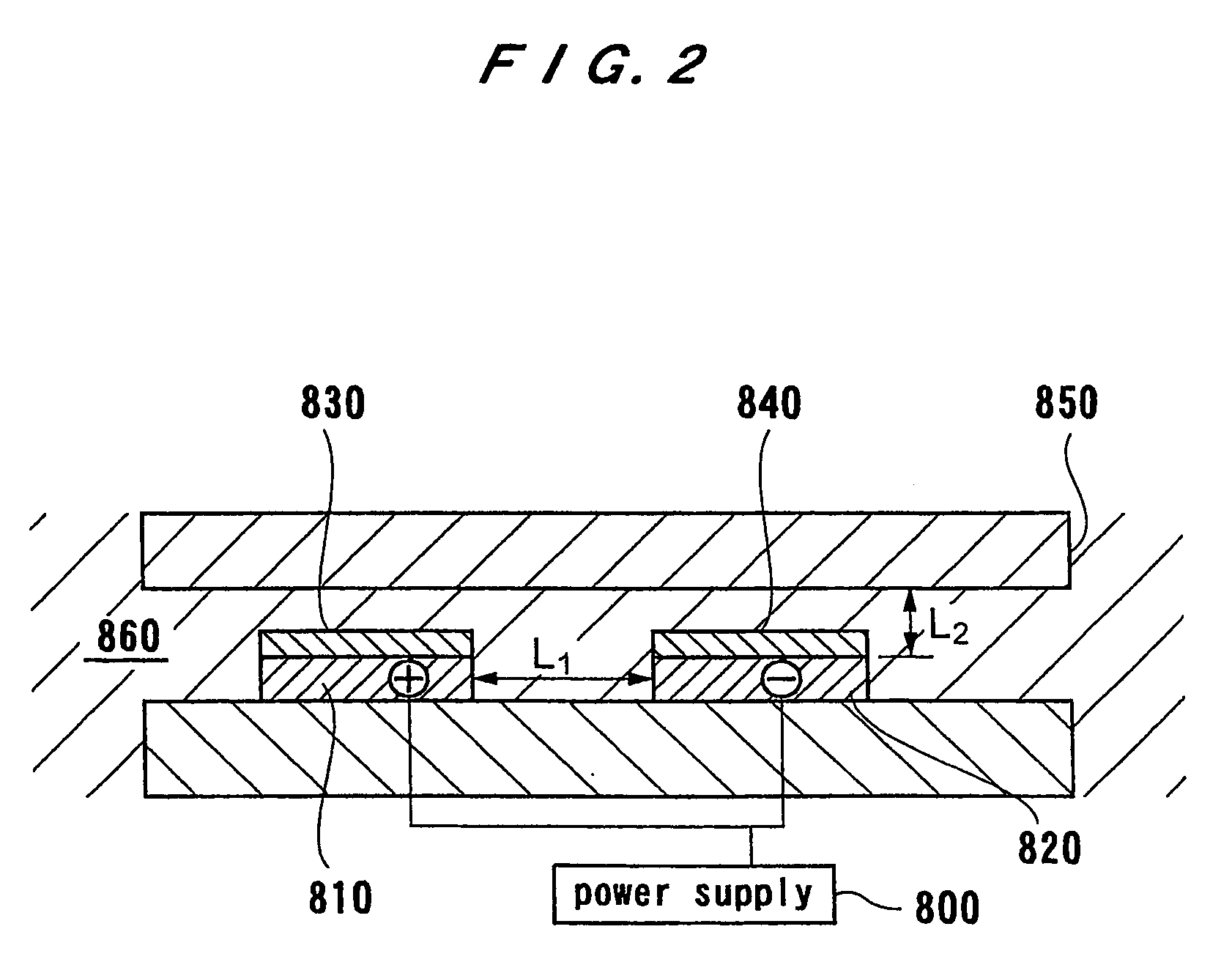
[0021] According to present invention, the ion exchange material having an ion exchange function can be formed directly on the electrode. Therefore, it is possible to reduce the distance between the electrode and the workpiece. Accordingly, it is possible to reduce the distance between the anode and the cathode. Thus, the electrolytic processing apparatus according to the present invention can flexibly cope with small electrodes and various shapes of electrodes. Further, because ion exchange materials can be formed separately on the cathode and the anode, a leakage current can be prevented from being produced between the cathode and the anode.

Problems solved by technology

Under these circumstances, in a conventional mechanical machining method in which a desired portion in a workpiece is physically destroyed and removed from a surface thereof by a tool, a large number of defects may be produced by the machining, thus deteriorating the properties of the workpiece.
Further, a conventional ion exchange fiber is problematic in that fibers may be removed from the ion exchanger during an electrolytic process so that the removed fibers cause variations of processing properties according to time elapsed.
It has been feared that seams of the fibers may have an influence on the surface roughness of the workpiece.
However, when an ion exchanger has an uneven thickness, the flatness of the surface of the workpiece may be influenced by the uneven thickness of the ion exchanger.

Method used


Image

  • Electolytic processing apparatus
  • Electolytic processing apparatus
  • Electolytic processing apparatus

Examples


Embodiment Construction

[0067] An electrolytic processing apparatus and a substrate processing apparatus having the electrolytic processing apparatus according to embodiments of the present invention will be described below with reference to the accompanying drawings. In the following embodiments, a substrate is used as a workpiece and processed by an electrolytic processing apparatus. However, the present invention is applicable to any workpiece other than the substrate.

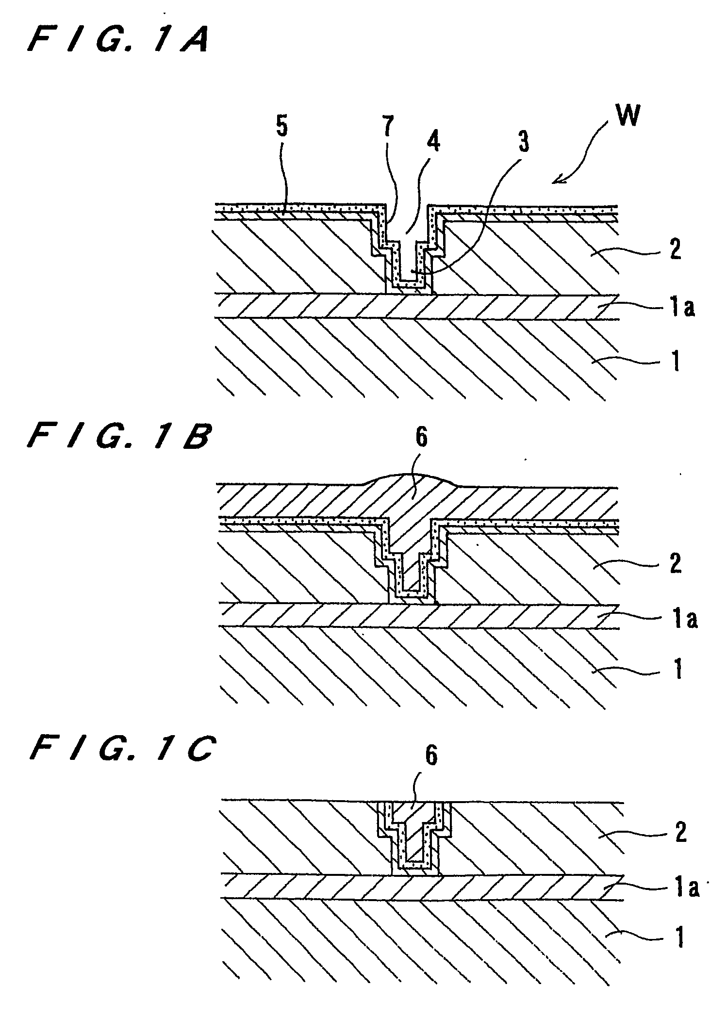
[0068]FIG. 5 is a plan view showing a substrate processing apparatus according to a first embodiment of the present invention. As shown in FIG. 5, the substrate processing apparatus has a pair of loading / unloading units 30, a reversing machine 32 for reversing a substrate, and an electrolytic processing apparatus 34. The loading / unloading units 30 serve as a loading and unloading section for loading and unloading a cassette accommodating the substrates. For example, as shown in FIG. 1B, the substrate W to be processed has a copper film 6 ...


PUM

PropertyMeasurementUnit
Electrical conductivityaaaaaaaaaa
Electrical conductoraaaaaaaaaa
Electric potential / voltageaaaaaaaaaa

Abstract

An electrolytic processing apparatus has at least one processing electrode (86) and at least feeding electrode (86) disposed on the same side as the processing electrode (86) with respect to a substrate (W). An organic compound having an ion exchange group is chemically bonded to at least one of a surface of the processing electrode (86) and a surface of the feeding electrode (86b) to form an ion exchanger (90). The electrolytic processing apparatus also has a substrate holder (42) for holding the substrate (W) and bringing the substrate (W) into contact with or close to the processing electrode (86). The electrolytic processing apparatus includes a power supply (48) for applying a voltage between the processing electrode (86) and the feeding electrode (86), and a fluid supply unit (92, 94) for supplying a fluid between the substrate (W) and the processing electrode (86).

Description

TECHNICAL FIELD [0001] The present invention relates to an electrolytic processing apparatus, and more particularly to an electrolytic processing apparatus useful for processing a conductive material formed on a surface of a substrate such as a semiconductor wafer or for removing impurities attached to a surface of a substrate. The present invention also relates to a substrate processing apparatus having such an electrolytic processing apparatus. BACKGROUND ART [0002] In recent years, there has been a growing tendency to replace aluminum or aluminum alloy as a metallic material for forming interconnection circuits on a substrate such as a semiconductor wafer with copper (Cu) having a low electric resistivity and a high electromigration resistance. Copper interconnections are generally formed by filling copper into fine recesses formed in a surface of a substrate. As methods for forming copper interconnections, there have been employed chemical vapor deposition (CVD), sputtering, and...

Claims


Application Information

Patent Timeline
IPC IPC(8): B23H3/04C25B11/00B23H3/02B23H9/00C25F7/00
CPCB23H3/02C25F7/00B23H9/00
Inventor TOMA, YASUSHIKOBATA, ITSUKI
Owner EBARA CORP
Learn More