
Devices and method for spectral measurements

a spectral measurement and encoded technology, applied in the field of multi-, encoded and weighted spectral measurements and devices, can solve the problems of limiting the utility of imagers, prior art imagers using single element detectors can exhibit more serious signal-to-noise ratio problems, and achieve the effect of increasing the need for photon throughput and high throughpu

Inactive Publication Date: 2006-05-04
PLAIN SIGHT SYST
View PDF3 Cites 55 Cited by
  • Summary
  • Abstract
  • Description
  • Claims
  • Application Information

AI Technical Summary

Benefits of technology

This approach enhances signal-to-noise ratios, reduces data collection time, and enables accurate analysis of rapidly changing sources and samples while minimizing noise contributions from source fluctuations, thereby improving the analytical capability and throughput of spectral measurements.

Problems solved by technology

Prior art imagers using a plurality of detectors at the image plane can exhibit serious signal-to-noise ratio problems.
Prior art imagers using a single element detector can exhibit more serious signal-to-noise ratio problems.
Signal-to-noise ratio problems limit the utility of imagers applied to chemical imaging applications where subtle differences between a sample's constituents become important.
However, the use of a plurality of detectors or the use of a macro moving grating has signal-to-noise limitations.
Each filter element employed can be very expensive, difficult to manufacture and all are permanently set at the time of manufacture in the wavelengths (bands) of radiation that they pass or reject.
Physical human handling of the filter elements can damage them and it is time consuming to change filter elements.
Clearly, however, this approach does not work in a more general case, and therefore it is desirable to have a controllable radiation source capable of providing arbitrary spectrum shapes and intensities.
A disadvantage of these systems is that they rely on an array of different LED elements (or lasers), each operating in a different, relatively narrow spectrum band.
In addition, there are technological problems associated with having an array of discrete radiation elements with different characteristics.
Thus, in certain prior art systems, a single sensor system may cost less to produce, but will take longer to fully measure an object under study.
In prior art multi-sensor systems, one often encounters a problem in which the different sensor elements have different response characteristics, and it is necessary to add components to the system to calibrate for this.
However, such devices are deficient in that the two slits required to help define the bandpass located both at the object and image plane of the optical system work to severely limit the amount of light that passes through the system, and therefore limit the amount of light that is measured.
For this reason, it is difficult or impossible to rapidly obtain good signal to noise ratios with monochromaters where high resolution is desired or in situations where there is a limit to the amount of light energy available.
However, the entrance slit still limits the amount light entering the system to each detector element in the linear detector array.
Such motion or change due to physical limitation of the conventional Hadamard spectrometer is generally subject to some variation, error and / or distortion over time, and is especially susceptible to errors in the presence of noise, heat, and other environmental or mechanical disturbances.
The linear array spectrometers and scanning monochromaters suffer from a lack of light throughput.
Conventional spectral measurement systems, such as the monochromaters, Hadamard spectrometers and Fourier transform spectrometers suffer from a complexity and instability due to the presence of moving or changing parts.
Since the latter spectral measurement systems make a series of measurements over time, rather than instantaneously, each suffers from errors when it is looking at the light sources or sample / matter that is changing during the time of measure or scan.
A further disadvantage of the scanning monochrometers, linear array spectrometers and Fourier transform spectrometer systems is that a contiguous regular interval of wavelength spectral data are collected.
In many spectrometric applications, such contiguous spectral data generally contains no relevant or useful information with respect to the spectral signature of the sample or matter.
In prior-art dispersive systems, as one moves to high resolution spectrometric measures one must decrease the slit width when preserving spectral bandwidth (spectral range) or increase the angular dispersion of the diffraction element and this results in a decrease of spectral range.
This decrease in photonic flux limits sensitivity, analytical capability and the ability of the detector to measure subtle differences in spectral energy at each data resolution element or related spectral resolution element.
The drawback to increasing the spectral resolution requirement that can apply to these conventional methods, even Hadamard and Fourier Transform multiplexed measurements, is that the scan times may need to be increased so that the integration times for each of the data resolution elements in the scan is sufficient to collect enough signal to rise above the noise floor of the system and to achieve the desired measure of the requisite signal-to-noise.
This requires an increase in scan time and can be problematic if the source energy or sample changes over the time T of the scan.
Despite the speed increase in scan times, these fast scan systems are inadequate for many measures such as looking at spark or combustion products during the life of a burn cycle.
Historically this has in large part been to the lack of availability, reliability, or affordability of appropriate detector arrays.
He also neglected to consider the possibilities of a linear array in similar configurations.

Method used


Image

  • Devices and method for spectral measurements
  • Devices and method for spectral measurements
  • Devices and method for spectral measurements

Examples


Embodiment Construction

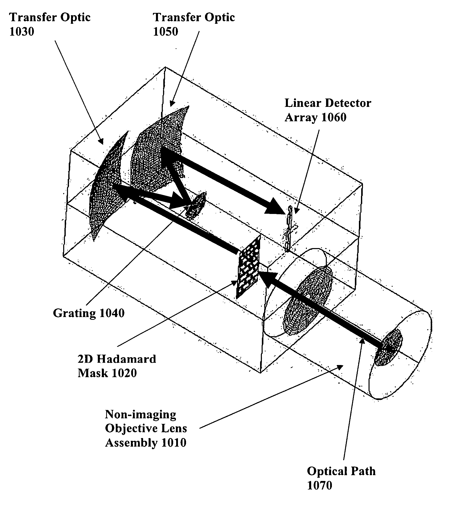
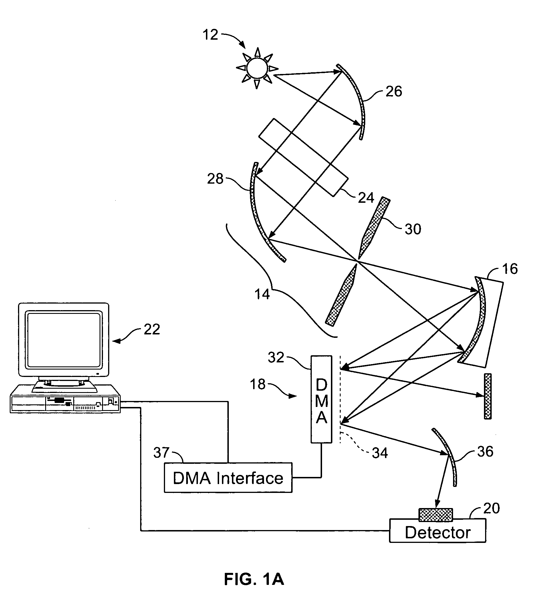
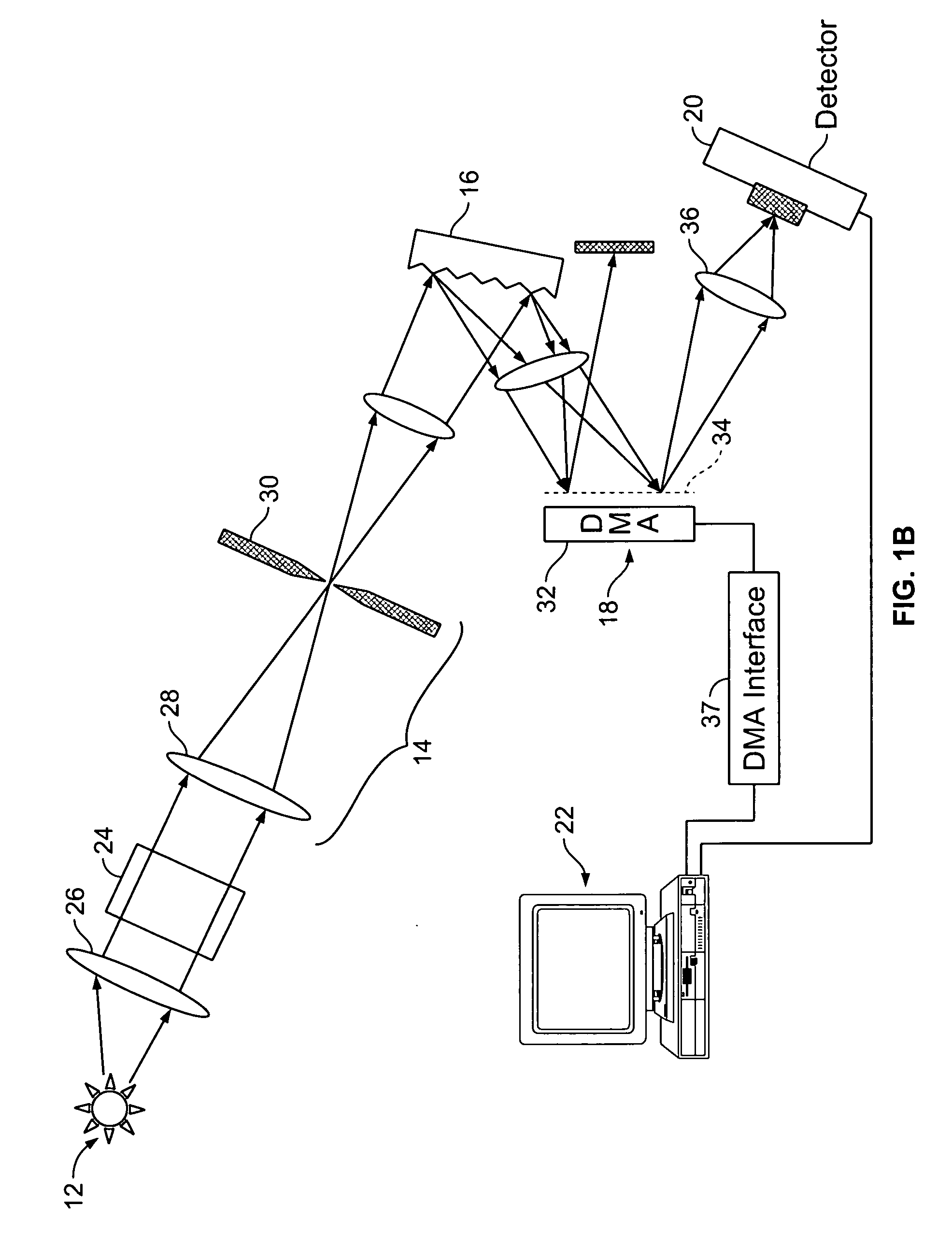
[0105] Turning now to the drawing figures and particularly FIG. 1A and 1B, a spectrometer assembly 10 constructed in accordance with one embodiment of the invention is illustrated. With reference to FIG. 1A the device broadly includes a source 12 of electromagnetic radiation, a mirror and slit assembly 14, a wavelength dispersing device 16, a spatial light modulator 18, a detector 20, and an analyzing device 22.

[0106] In particular, the electromagnetic radiation source 12 is operable to project rays of radiation onto or through a sample 24 that is to be analyzed, such as a sample of body tissue or blood. The radiation source can be any device that generates electromagnetic radiation in a known wavelength spectrum such as a globar, hot wire, or light bulb that produces radiation in the infrared spectrum. To increase the amount of rays that are directed to the sample, a parabolic reflector 26 can be interposed between the source 12 and the sample 24. In a specific embodiment, the sou...


PUM


Abstract

A spectral measurement device comprising an entrance aperture for receiving an electromagnetic energy and a mask located at the entrance aperture in the form of a two-dimensional encodement pattern. An optical element conditions the electromagnetic energy received from the mask for presentation to the spectral dispersion element and the and a spectral dispersion element disperses the electromagnetic energy in one or more dimensions. Additionally, the optical element conditions the dispersed electromagnetic energy onto an array of detector elements.

Description

RELATED APPLICATION [0001] This application claims priority benefit of provisional patent application No. 60 / 615,724, filed Oct. 4, 2004, which is incorporated by reference in its entirety. This application is a continuation of application Ser. No. 11 / 075,114, filed Mar. 7, 2005, which claims priority benefit of provisional patent application No. 60 / 550,966, filed Mar. 6, 2004 and is a continuation-in-part of application Ser. No. 10 / 832,684, filed Apr. 26, 2004, which is a divisional of application Ser. No. 09 / 798,860, filed Mar. 1, 2001, now U.S. Pat. No. 6,859,275, which is a continuation-in-part of application Ser. No. 09 / 672,257, filed Sep. 28, 2000, now U.S. Pat. No. 6,392,748, which is a continuation of application Ser. No. 09 / 502,758 filed Feb. 11, 2000, now U.S. Pat. No. 6,128,078, which is a continuation of application Ser. No. 09 / 289,482 filed Apr. 9, 1999, now U.S. Pat. No. 6,046,808, each of which is incorporated by reference in its entirety.FIELD OF THE INVENTION [0002]...

Claims


Application Information

Patent Timeline
Patent Type & Authority Applications(United States)
IPC IPC(8): G01J3/28G01J3/02G01J3/18G01J3/42
CPCG01J3/02G01J3/0208G01J3/021G01J3/0218G01J3/0229G01J3/027G01J3/04G01J3/10G01J3/18G01J3/2803G01J3/2823G01J3/2846G01J3/36G01J3/42G01J2001/4242
Inventor GESHWIND, FRANKCOIFMAN, RONALD R.COPPI, ANDREASDEVERSE, RICHARD A.FATELEY, WILLIAM G.
Owner PLAIN SIGHT SYST
Learn More