Separation of carbon dioxide (CO2) from gas mixtures by calcium based reaction separation (CaRS-CO2) process

Active Publication Date: 2006-05-04
THE OHIO STATES UNIV
View PDF73 Cites 78 Cited by
  • Summary
  • Abstract
  • Description
  • Claims
  • Application Information

AI Technical Summary

Benefits of technology

[0021] The present invention includes a calcium oxide, its usage for the separation of CO2 from multicompone

Problems solved by technology

Although the anthropogenic CO2 emissions are small compared to the amount of CO2 exchanged in the natural cycles, the discrepancy between the long life of CO2 in the atmosphere (50-200 years) and the slow rate of natural CO2 sequestration processes leads to CO2 build up in the atmosphere.
The dominating costs associated with the current CO2 separation technologies necessitate development of economical alternatives.
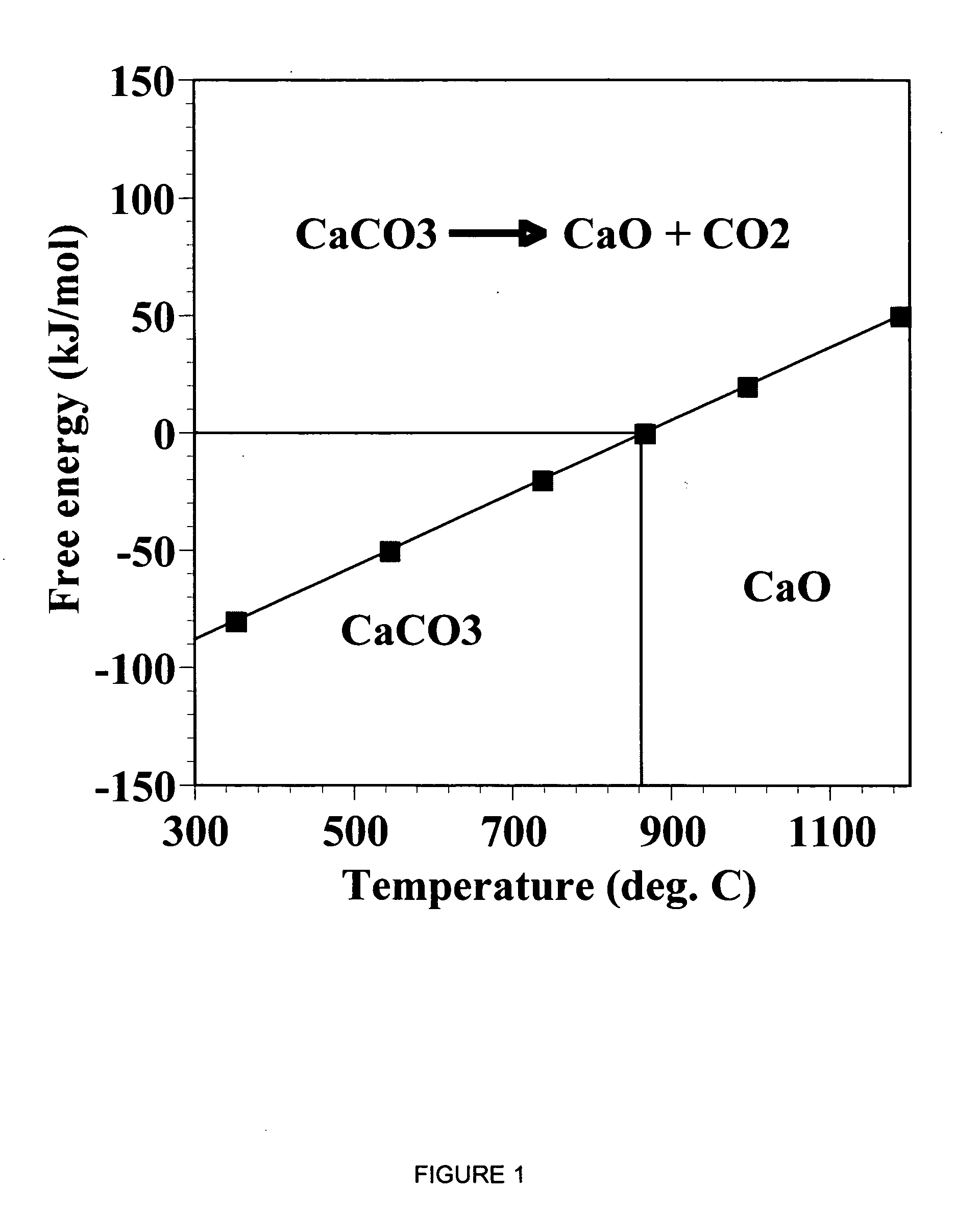
However, at lower temperatures, the carbonation reaction is kinetically slow.
his layer hinders the inward diffusion of CO2 and the outward diffusion of H2O (a product of the carbonation reaction) leading to low conversions. T
However, the structural limitations prevent the attainment of theoretical conversion.
However, the extent of carbonation at lower temperature/pressure conditions that are more characteristic of CO2 containing gaseous mixtures is absent in their work.
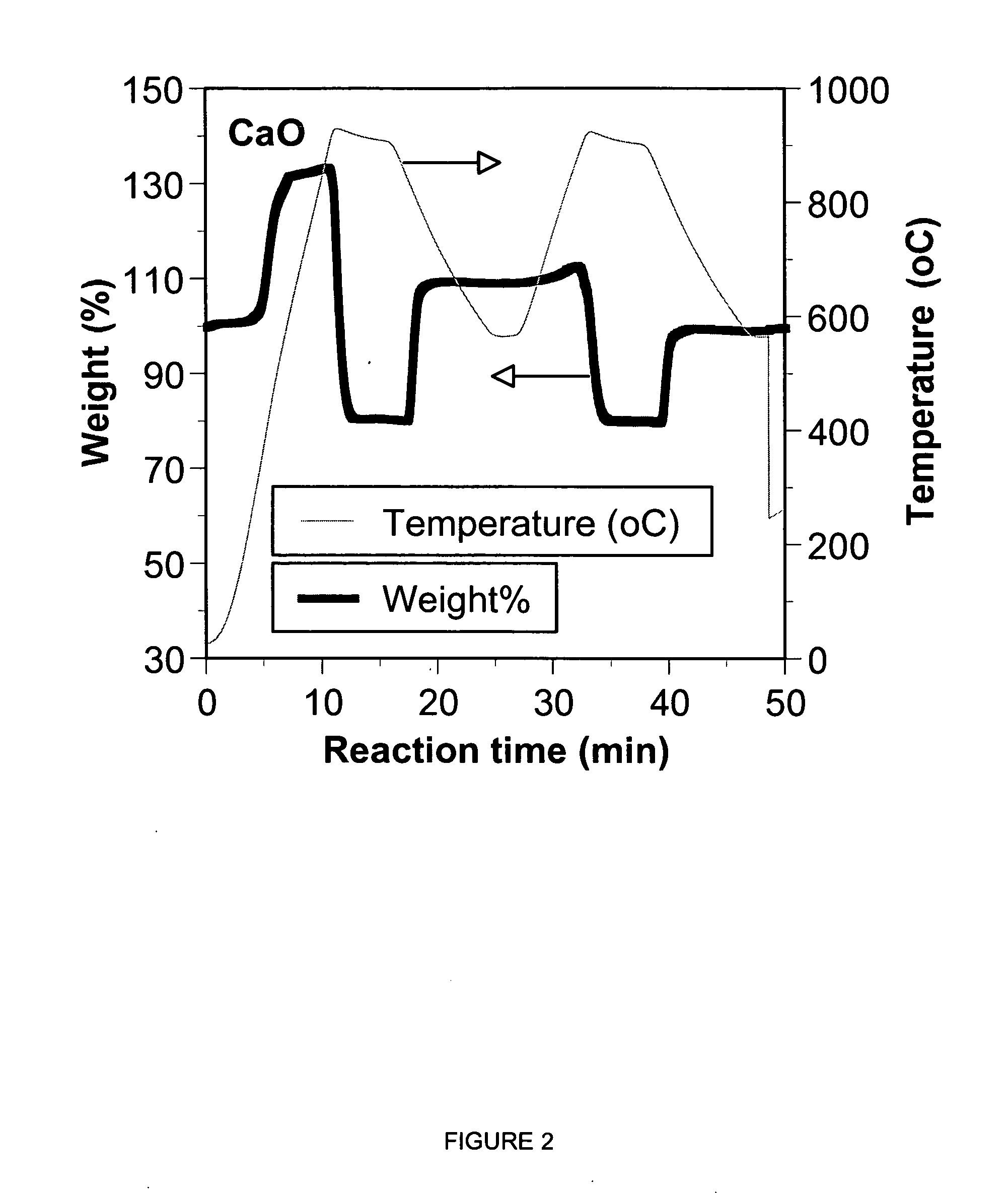
The limitation in total conversion stems essentially from the nature of the initial pore size distribution of the CaO sorbent.
However, the biggest issue that needs to be addressed for the success of the hydrogen-based economy involves the source of hydrogen itself.
However, water ele

Method used


Image

  • Separation of carbon dioxide (CO2) from gas mixtures by calcium based reaction separation (CaRS-CO2) process
  • Separation of carbon dioxide (CO2) from gas mixtures by calcium based reaction separation (CaRS-CO2) process
  • Separation of carbon dioxide (CO2) from gas mixtures by calcium based reaction separation (CaRS-CO2) process

Examples


Embodiment Construction

)

[0079] In accordance with the foregoing summary, the following presents a detailed description of the preferred embodiment(s) of the invention that are currently considered to be the best mode.

Chemicals, Sorbents and Gases

[0080] Naturally occurring limestone (CaCO3) and hydrated lime (Ca(OH)2), synthesized from it were obtained from Linwood Mining and Minerals. Dolomite (CaCO3.MgCO3) was procured from the National Dolomite Company. The purity of these ores was above 90%. High purity metal oxides such as ZnO, MgO, MnO2, NiO, CuO, PbO, CaO were obtained from Aldrich Chemical Company. Precipitated calcium carbonate (PCC) was synthesized from Linwood hydrate by the procedure described in a following section. N40V® dispersant, a sodium salt of a carboxylic acid, used in the synthesis of PCC was obtained from Allied Colloid. The synthesis procedure is described in detail in a following section. N2 and CO2 used for calcination and carbonation experiments were 99.999% and 99.9% pure, res...


PUM

PropertyMeasurementUnit
Fractionaaaaaaaaaa
Massaaaaaaaaaa
Massaaaaaaaaaa

Abstract

A reaction-based process has been developed for the selective removal of carbon dioxide (CO2) from a multicomponent gas mixture to provide a gaseous stream depleted in CO2 compared to the inlet CO2 concentration in the stream. The proposed process effects the separation of CO2 from a mixture of gases (such as flue gas/fuel gas) by its reaction with metal oxides (such as calcium oxide). The Calcium based Reaction Separation for CO2 (CaRS—CO2) process consists of contacting a CO2 laden gas with calcium oxide (CaO) in a reactor such that CaO captures the CO2 by the formation of calcium carbonate (CaCO3). Once “spent”, CaCO3 is regenerated by its calcination leading to the formation of fresh CaO sorbent and the evolution of a concentrated stream of CO2. The “regenerated” CaO is then recycled for the further capture of more CO2. This carbonation-calcination cycle forms the basis of the CaRS—CO2 process. This process also identifies the application of a mesoporous CaCO3 structure, developed by a process detailed elsewhere, that attains >90% conversion over multiple carbonation and calcination cycles. Lastly, thermal regeneration (calcination) under vacuum provided a better sorbent structure that maintained reproducible reactivity levels over multiple cycles.

Description

RELATED APPLICATION DATA [0001] This application is a continuation-in-part of and claims the priority benefit of U.S. patent application Ser. No. 10 / 359,763 Feb. 6, 2003, which is hereby incorporated herein by reference.TECHNICAL FIELD OF THE INVENTION [0002] The present invention relates to the application of chemical sorbents for the separation of CO2 from gas mixtures. BACKGROUND OF THE INVENTION [0003] As used herein, the term “supersorbent” shall mean a sorbent as taught in U.S. Pat. No. 5,779,464 entitled “Calcium Carbonate Sorbent and Methods of Making and Using Same”, the teachings of which are hereby incorporated by reference. [0004] As used herein, the term “microporous” shall mean a pore size distribution of less than 5 nanometers. As used herein, the term “mesoporous” shall mean a pore size distribution of from about 5 nanometers to about 20 nanometers. [0005] Atmospheric CO2 concentration has been increasing steadily since the industrial revolution. It has been widely a...

Claims


Application Information

Patent Timeline
IPC IPC(8): B01D53/62
CPCB01D53/1475B01J20/3466B01D53/62B01D2251/404B01D2253/10B01D2257/504B01J20/041B01J20/06B01J20/28057B01J20/28071B82Y30/00C01F11/06C01P2002/32C01P2002/72C01P2006/12C01P2006/14C01P2006/17C10J3/482C10J2300/0996C10J2300/1807H01M8/0668H01M2008/1293Y02C10/04Y02C10/06Y02C10/08B01J8/06C10K1/024C10K3/04Y02E60/525B01D53/508B01J20/3085B01J20/3433B01J20/3483B01D53/1493Y02C20/40Y02P20/151Y02E60/50
Inventor FAN, LIANG-SHIHGUPTA, HIMANSHUIYER, MAHESH V.
Owner THE OHIO STATES UNIV
Why Eureka
Try Eureka