Method of producing a microfluidic device

a microfluidic device and microfluidic technology, applied in the field of miniature instruments, can solve problems such as partial melting of substrate materials along the applied pattern

Inactive Publication Date: 2006-05-11
CRANFIELD UNIVERSITY
View PDF10 Cites 13 Cited by
  • Summary
  • Abstract
  • Description
  • Claims
  • Application Information

AI Technical Summary

Benefits of technology

[0004] The present invention enables one to provide microfluidic devices that combine the advantages of microfluidics with improved material handling characteristics and reduced costs for manufacturing.
[0014] The formation and maintenance of the integrated microchannel network in the interior part of the microfluidic device may be achieved by patterned direction of energy, e.g. heat or light into the interior part of microfluidic device. This application of energy results in partial melting of the substrate material of the interior part of the device according to a preset pattern in a way that ensures that the liquid channels are formed between the top and the bottom parts of the device. In different formats of the microfluidic device the energy will be applied to the interior part in different ways, including using light (e.g. a laser beam), heat (using e.g. IR laser), focused ionic, particle, X-ray and electron beams. In some embodiments the patterning will be achieved by focusing energy beams in pre-determined parts of the interior part through a transparent part of the casing or by using masks, which restrict the direction of energy to the predetermined areas of the interior part only. The advantages of the approach, described in this invention lies in the flexibility of the system. The pattern (and the patterned system of created microchannels) can be changed by re-focusing and re-directing the applied energy. The microchannel network will exist only when the energy is applied to corresponding areas. When the application of energy stops—the liquid in the channel will be frozen and channel will disappear. A plurality of integrated microchannels, including transverse channels, cross intersections, “T” intersections, etc., in the same microfluidic device can be created for a variety of specific applications. The microchannel network can also be modified in real time during the analytical or separation method to facilitate or promote individual stages of the experiment or analysis. The connection between the channels, reservoirs, ports for fluid communications and electrodes can be easily established or terminated by focusing energy at appropriate connection points.

Problems solved by technology

The microchannel network is created and maintained in the body structure by directing patterned energy flow, which results in partial melting of substrate material along the applied pattern.

Method used


Image

  • Method of producing a microfluidic device
  • Method of producing a microfluidic device
  • Method of producing a microfluidic device

Examples


example 1

[0031] An ice crystal (2×2×2 cm) was illuminated with a 40 W CO2 laser for 5 minutes. At the end of illumination it was found that a cylindrical hole of diameter 3 mm had been drilled through the crystal.

example 2a

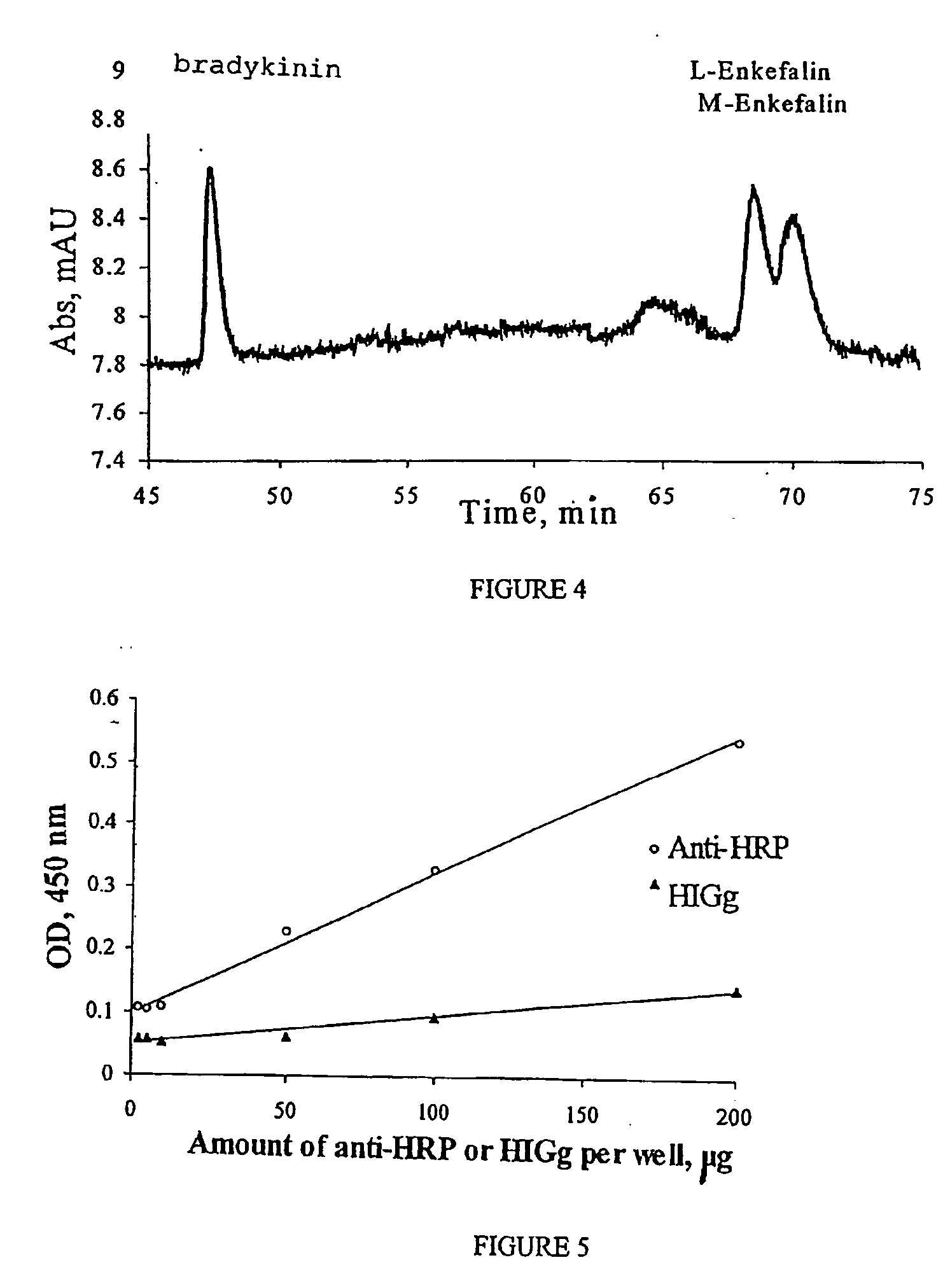
[0032] A 60 cm glass capillary (75 μm internal diameter) was filled with 10 mM HCl and frozen at −20° C. The capillary was mounted in a Waters 4000 E capillary electrophoresis instrument supplied with a thermostat. The applied potential was 10000 V and the temperature was maintained at −20° C. After I hour an internal part of the ice in capillary had been melted due to the applied potential, and the current passing through the system increased to 0.2 μA, after which it stabilised. A solution containing 1 mg / ml of each of bradykinin, L-enkefalin and M-enkefalin was injected into the capillary by hydrostatic pressure. The electropherogram which shows the achieved separation on ice-filled capillary is presented in FIG. 4.

example 2b

[0033] A 60 cm glass capillary (75 μm internal diameter) was filled with 10 mM HCl and frozen at −20° C. The capillary was mounted in Waters 4000 E capillary electrophoresis instrument supplied with thermostat. The applied potential was 10000 V and the temperature was maintained at −5° C. The current passing through the system stabilised at 1.5 μA which is an indication that ice has not been formed in the capillary. A mixture of bradykinin, L-enkefalin and M-enkefalin was injected into the capillary as in Example 2a. No separation was observed in this case due to absence of ice in capillary.


PUM

PropertyMeasurementUnit
diameteraaaaaaaaaa
internal diameteraaaaaaaaaa

Abstract

The present invention provides a microfluidic device comprising a body structure which comprises a fusible material. Selective application of energy (e.g. scanning radiation) produces and maintains a network of microchannels by fusing the material. There may be pons in fluid communication with one or more channels. The subject devices find use in a variety of electrophoretic applications, including clinical assays, high throughput screening for genomics, proteomics and pharmaceutical applications, point-of-care in vitro diagnostics, molecular genetic analysis and nucleic acid diagnostics, cell separations, and bioresearch generally.

Description

TECHNICAL FIELD [0001] The present invention relates generally to miniature instrumentation for chemical / biochemical analysis and chemical / biological sensing and, more specifically, to microfluidic devices, their production and use. It is particularly concerned with methods for creating microchannels, and to controlled manipulations of fluids and capillaries in microchannels. These microchannels and tools for their creating and manipulation can be used in a variety of applications, including capillary electrophoresis, liquid chromatography, and flow injection analysis. BACKGROUND ART [0002] Microfluidic systems have become increasingly popular tools in electronics, biotechnology, and the pharmaceutical and related industries where they provide numerous advantages, including significantly smaller reagent requirements, high speed of analysis and the possibility for automation [U.S. Pat. No. 6,251,343 and U.S. Pat. No. 6,379,974]. Typical examples of such microfluidic devices are a min...

Claims


Application Information

Patent Timeline
Patent Type & Authority Applications(United States)
IPC IPC(8): B01L3/00
CPCB01L3/502707B01L2200/147B01L2300/0816B01L2300/165B01L2300/18B01L2400/0415Y10T436/2575B01L2400/0487B01L2400/0677B81B2201/058B81B2203/0338B81C1/00119B81C2201/0143B01L2400/0472
Inventor BOSSI, ALESSANDRAFRANCIS, ANTHONY PETERIMIRIYNA, OLENA VOLODPILETSKY, SERGEY A.
Owner CRANFIELD UNIVERSITY
Why Eureka
Try Eureka