
Non-aqueous electrolyte secondary battery

a secondary battery, non-aqueous electrolyte technology, applied in the direction of cell components, final product manufacturing, sustainable manufacturing/processing, etc., can solve the problems of increasing the contact resistance among particles in the negative electrode, degrading the current collecting network, and significant problems to be solved, etc., to achieve excellent charge/discharge cycle characteristics, excellent cycling characteristics, and high capacity

Active Publication Date: 2006-05-18
PANASONIC CORP
View PDF13 Cites 31 Cited by
  • Summary
  • Abstract
  • Description
  • Claims
  • Application Information

AI Technical Summary

Benefits of technology

[0027] According to the invention, it is possible to provide a non-aqueous electrolyte secondary battery that has a high capacity and excellent charge / discharge cycle characteristics, and particularly, that has excellent cycling characteristics even when the battery is rapidly charged and discharged. An alloying material with the above-described constitution is thought to have an improved resistance to expansion upon charge.
[0028] When the content of the A phase in the alloying material is 40 to 95% by weight, an extremely high capacity is achieved, but the expansion rate upon charge is considered to be significantly high. Even in cases of such large expansion, the above-described construction suppresses degradation of the current collecting network. In particular, when the B phase contains at least one selected from the group consisting of Ti, Zr, Ni, Cu, and Fe, cracking of the particles of alloying material is unlikely to occur during charging, and excellent cycle characteristics can be achieved even in cases of rapid charge / discharge.
[0029] It is desirable to granulate the alloying material so as to have a proper particle size distribution. The use of an alloying material having a proper particle size distribution allows homogeneous distribution of the active material inside the negative electrode. Hence, the expansion and contraction of the negative electrode upon charge and discharge also become even, which is advantageous to the cycle life of the non-aqueous electrolyte secondary battery. Also, the use of an alloying material having a proper particle size distribution can provide a negative electrode with a sufficient density (electrode mixture density), thus being advantageous to heightening the capacity of the non-aqueous electrolyte secondary battery.

Problems solved by technology

Although Si is capable of realizing a high capacity negative electrode, it has a significant problem to be solved with respect to the charge / discharge cycle characteristics of the resultant battery.
The problem is that during charge and discharge reactions, the absorption and desorption of lithium involves repeated expansion and contraction of Si, thereby increasing the contact resistance among particles in the negative electrode and degrading the current collecting network.
Such degraded current collecting network becomes a major factor that causes shortening of charge / discharge cycle life.
Therefore, these techniques are effective to a certain extent in suppressing the degradation of the current collecting network, which is a major factor causing the degradation of cycle characteristics.
However, a detailed examination of these related art techniques has revealed that the techniques may not produce sufficient suppression of cycle characteristic deterioration when batteries are rapidly charged and discharged at a relatively large current.
Thus, the energy density per unit volume becomes low and the battery capacity also becomes small.
Accordingly, this is disadvantageous to the cycle characteristics and storage characteristics.
Hence, intercalation and deintercalation of lithium upon charge and discharge become uneven inside the electrode, which is disadvantageous to the cycle life of the battery.
That is, the proposals of U.S. Pat. No. 6,090,505 and Japanese Laid-Open Patent Publication No. 2004-103340 and No. 2004-335272 have a problem with respect to a rapid charge / discharge at a large current.
The proposals of Japanese Laid-Open Patent Publication No. 2003-109590, No. 2004-185810, No. 2004-214055, and No. 2000-36323 have a problem with regard to the balance between capacity and cycle characteristics.
Particularly when the negative electrode is produced by molding a negative electrode mixture into a pellet, it is difficult to obtain a non-aqueous electrolyte secondary battery with a high capacity and excellent cycle characteristics.

Method used


Image

  • Non-aqueous electrolyte secondary battery
  • Non-aqueous electrolyte secondary battery

Examples


example 1

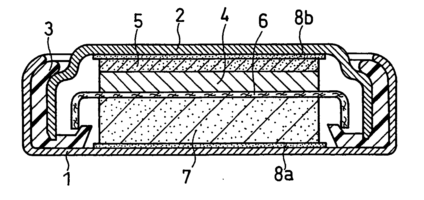
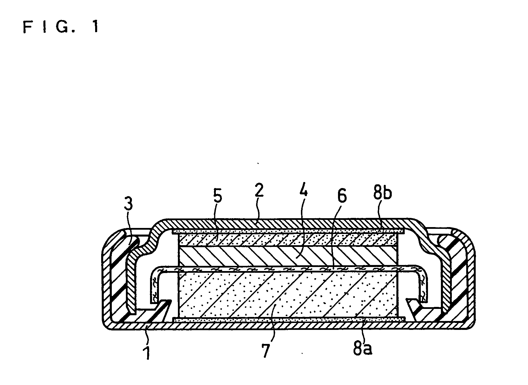
[0087] In Examples and Comparative Examples, negative electrodes and coin-shaped batteries were produced in the following manner, and their cycle life and discharge capacity were evaluated.

(1) Alloying Material Preparation

[0088] Ti, Zr, Ni, Cu, and Fe were used in metallic form as raw materials for the transition metal element M. Each metal was in powder form having a purity of 99.9% and a particle size of 100 to 150 μm. Also, a Si powder having a purity of 99.9% and a mean particle size of 3 μm was used as the raw material for Si.

[0089] These raw materials were mixed together in the following weight ratios such that the weight of the A phase relative to the total weight of the A phase and the B phase in the resultant alloying material would amount to approximately 80% on the assumption that MSi2 would form as the B phase.

[0090] Ti:Si=9.2:90.8

[0091] Zr:Si=12.4:87.6

[0092] Ni:Si=10.2:89.8

[0093] Cu:Si=10.6:89.4

[0094] Fe:Si=10.2:89.8

[0095] Each powder mixture of 3.5 kg was pla...

example 2

[0123] In this example, the crystallite size of alloying materials was examined in detail.

[0124] The crystallite size of alloying materials was varied as shown in Table 3 below by changing the conditions of the mechanical alloying operation (frequency and operation time). In the same manner as in Example 1 except for the variations in crystallite size, various alloying materials were produced such that the weight ratio between the A phase and B phase would be 80:20. These alloying materials were then classified, to obtain a Ti-Si alloying material, a Zr—Si alloying material, a Ni—Si alloying material, a Cu—Si alloying material and an Fe—Si alloying material, each having a maximum particle size of 8 μm and a mean particle size of 5 μm.

[0125] In the same manner as in Example 1, the crystallite size of the A phase was calculated from the half width of the most intense peak obtained by X-ray diffraction analysis of each alloying material and the Scherrer equation.

[0126] In Table 3, a...

example 3

[0135] In this Example, in a diffraction spectrum obtained by performing an X-ray diffraction analysis of an alloying material with CuKα rays as the radiation source, the half width of the most intense diffraction peak in the range of diffraction angle 2θ=10° to 80° was examined in detail.

[0136] The half width of the most intense diffraction peak was varied as shown in Table 4 below by changing the conditions of the mechanical alloying operation (frequency and operation time). In the same manner as in Example 1, except for the variations in half width, various alloying materials were produced such that the weight ratio between the A phase and B phase would become 80:20. These materials were then classified, to obtain a Ti—Si alloying material, a Zr—Si alloying material, a Ni—Si alloying material, a Cu—Si alloying material and an Fe—Si alloying material, each having a maximum particle size of 8 μm and a mean particle size of 5 μm.

[0137] In Table 4, although the half width of only t...


PUM

PropertyMeasurementUnit
Lengthaaaaaaaaaa
Fractionaaaaaaaaaa
Fractionaaaaaaaaaa

Abstract

A non-aqueous electrolyte secondary battery that has a high electrical capacity and exhibits excellent cycle characteristics even when the battery is rapidly charged and discharged at a large current includes: a positive electrode capable of reversibly absorbing and desorbing Li; a negative electrode; and a non-aqueous electrolyte. The negative electrode includes an alloying material that is capable of electrochemically absorbing and desorbing Li, and includes an A phase composed mainly of Si and a B phase including an intermetallic compound of at least one transition metal element and Si. The transition metal element is selected from the group consisting of Ti, Zr, Ni, Cu, and Fe. At least one of the A phase and the B phase includes a microcrystalline or amorphous region. The weight percent of the A phase relative to the total weight of the A phase and the B phase is greater than 40% and not greater than 95%.

Description

FIELD OF THE INVENTION [0001] The present invention relates to an improvement in the negative electrode of a non-aqueous electrolyte secondary battery. The present invention provides a non-aqueous electrolyte secondary battery having a high electrical capacity and excellent charge and discharge (hereinafter referred to as “charge / discharge”) cycle characteristics. BACKGROUND OF THE INVENTION [0002] Non-aqueous electrolyte secondary batteries can realize high voltage and high energy density, so they have been researched extensively. Positive electrodes of non-aqueous electrolyte secondary batteries include a transition metal oxide or a transition metal chalcogenide, such as LiMn2O4, LiCoO2, LiNiO2, V2O5, Cr2O5, MnO2, TiS2, or MoS2. Such material has a layered or tunnel-like crystal structure into and from which lithium ions are intercalated and deintercalated. The negative electrodes typically include a carbon material. Although a carbon material typically has a relatively small capa...

Claims


Application Information

Patent Timeline
IPC IPC(8): C25B11/04H01M4/02H01M4/134H01M10/052H01M10/058H01M10/36
CPCH01M2/0222H01M4/134H01M4/38H01M10/052H01M10/058H01M2004/021Y02E60/122H01M4/386H01M50/109Y02E60/10Y02P70/50H01M4/02
Inventor BITO, YASUHIKOSATO, TOSHITADAYAMAMOTO, TERUAKIUEDA, TOMOHIRO
Owner PANASONIC CORP
Learn More