
Scalable integrated logic and non-volatile memory

a non-volatile memory, integrated logic technology, applied in the field of memory and logic devices, can solve the problems of low integration of embedded drams, volatile dram cells, data loss, etc., and achieve the effect of high performan

Active Publication Date: 2006-05-25
MICRON TECH INC
View PDF4 Cites 88 Cited by
  • Summary
  • Abstract
  • Description
  • Claims
  • Application Information

AI Technical Summary

Benefits of technology

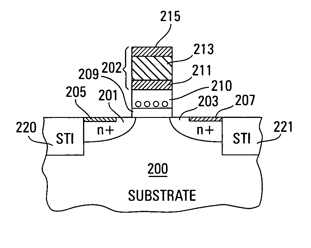
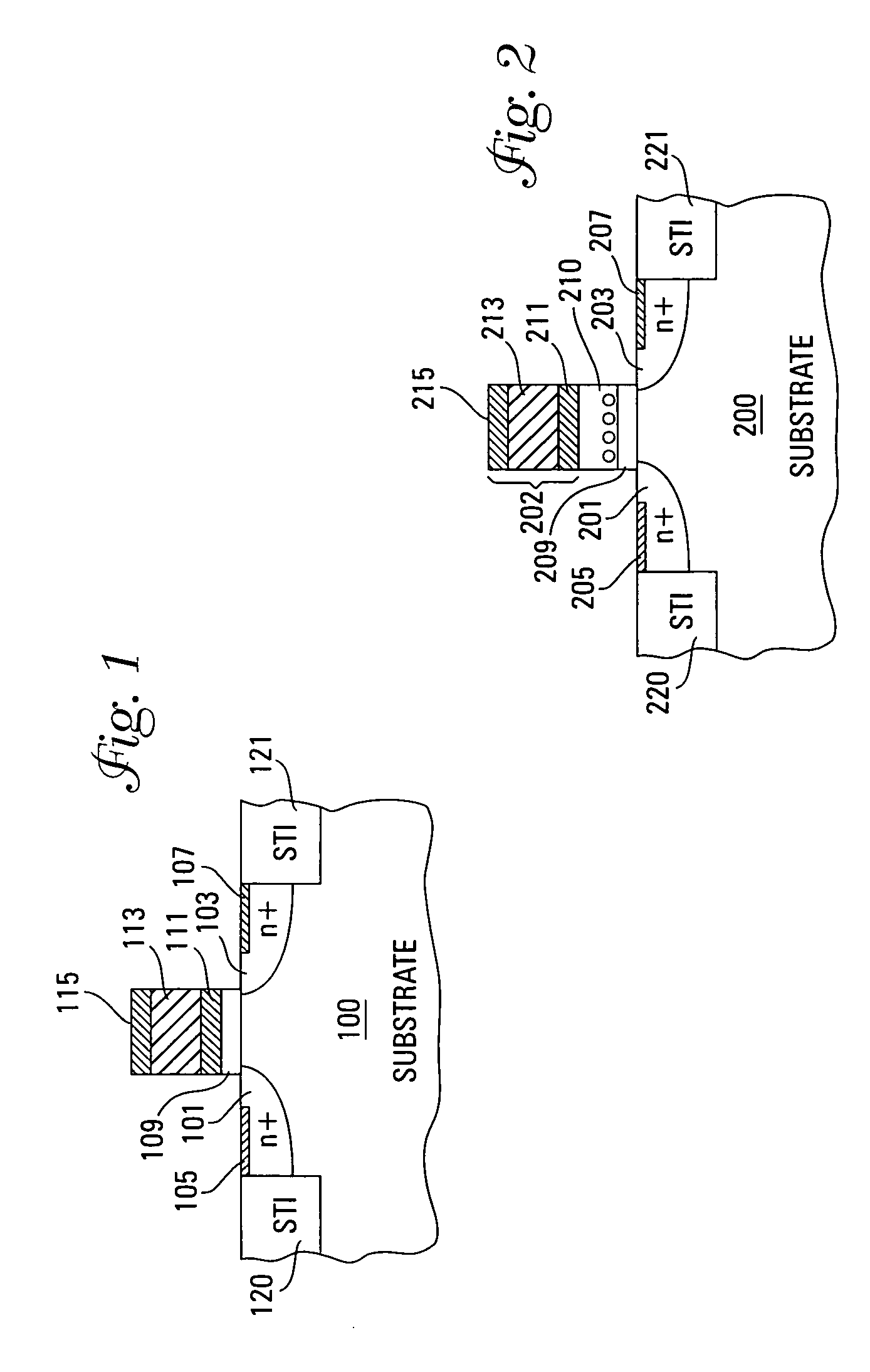
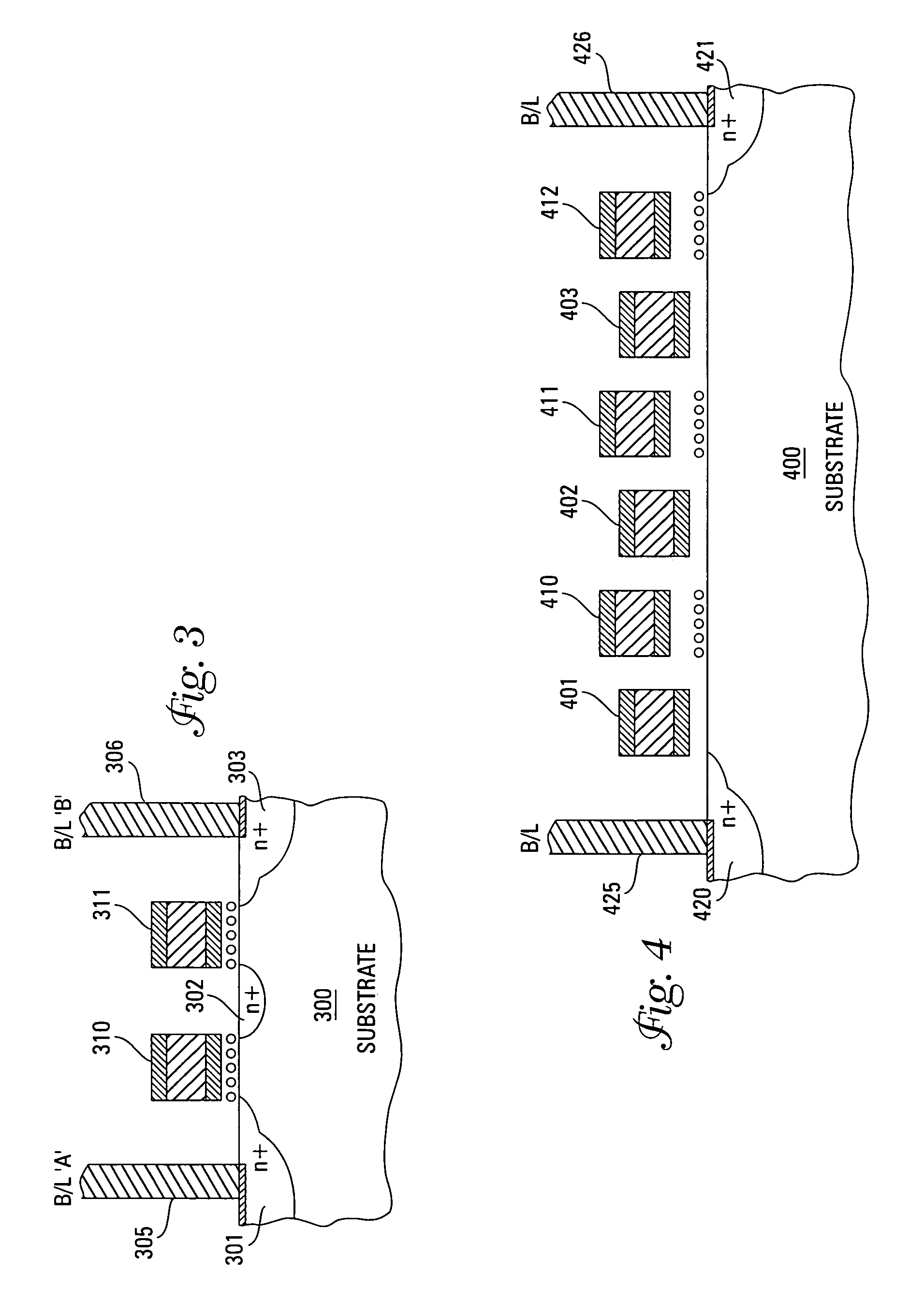
[0012] For the non-volatile memory transistor element, an additional high-k insulator layer with embedded metal dots near the gate insulator interface is incorporated between the gate insulator and the gate stack. In this manner, a flash memory cell that is compatible and scalable with the logic transistor is created. Both transistors are formed using a low temperature process integration scheme to ensure high performance.

Problems solved by technology

DRAM cells are volatile and therefore lose data when the power is removed.
Additionally, due to leakage, the capacitor must be refreshed periodically to maintain the charge.
At thicknesses below 5 nm, leakage through the oxide becomes appreciable thus providing constraints and challenges towards further scalability from the standpoint of power, speed, and circuit reliability.
Integration of embedded DRAM below 100 nm node has been a challenge not only due to capacitor scalability concerns of DRAM cells but also because of the requirement for higher thermal budgets to achieve leakage, yield, and density objectives of the embedded DRAM cells.
However, conventional floating gate flash memory technology has not been scalable in power supply voltage levels, consumes higher than desired power during programming, and also requires high programming voltages (e.g., 10-20V for the 100 nm technology node).
Embedding such a device requires on-chip generation of the high voltages and routing these voltages in an otherwise scaled low voltage logic technology adds considerable process complexity and cost and compromises functionality.

Method used


Image

  • Scalable integrated logic and non-volatile memory
  • Scalable integrated logic and non-volatile memory
  • Scalable integrated logic and non-volatile memory

Examples


Embodiment Construction

[0019] In the following detailed description of the invention, reference is made to the accompanying drawings that form a part hereof and in which is shown, by way of illustration, specific embodiments in which the invention may be practiced. In the drawings, like numerals describe substantially similar components throughout the several views. These embodiments are described in sufficient detail to enable those skilled in the art to practice the invention. Other embodiments may be utilized and structural, logical, and electrical changes may be made without departing from the scope of the present invention. The following detailed description is, therefore, not to be taken in a limiting sense, and the scope of the present invention is defined only by the appended claims and equivalents thereof. The terms wafer or substrate used in the following description include any base semiconductor structure. Both are to be understood as including silicon-on-sapphire (SOS) technology, silicon-on-...


PUM


Abstract

A scalable, logic transistor has a pair of doped regions for the drain and source. A gate insulator layer is formed over the substrate and between the drain and source regions. A gate stack is formed of a gate layer, such as polysilicon or metal, between two metal nitride layers. A compatible non-volatile memory transistor can be formed from this basic structure by adding a high-K dielectric constant film with an embedded metal nano-dot layer between the tunnel insulator and the gate stack.

Description

TECHNICAL FIELD OF THE INVENTION [0001] The present invention relates generally to memory and logic devices and in particular the present invention relates to scalable non-volatile memory devices in logic technology environment. BACKGROUND OF THE INVENTION [0002] Memory and logic devices are typically provided as internal, semiconductor, integrated circuits in computers and many other electronic devices including handheld devices such as cellular telephones and personal digital assistants. There are many different types of memory including static random-access memory (SRAM), read only memory (ROM), flash memory, dynamic random access memory (DRAM), and synchronous dynamic random access memory (SDRAM) that are functionally integrated with logic devices such as microprocessors, microcontrollers, digital signal processors, programmable logic devices, wireless communication, and networking. [0003] Many current and future devices require increasing integration of logic and memory functio...

Claims


Application Information

Patent Timeline
IPC IPC(8): H01L21/8234
CPCB82Y10/00H01L29/42332H01L29/4966H01L29/66825H01L29/517
Inventor BHATTACHARYYA, ARUP
Owner MICRON TECH INC
Learn More