In-plane distribution measurement method

a distribution measurement and in-plane technology, applied in the field of in-plane distribution measurement method, can solve the problems of general difficulty in identifying the original structure, inability to directly estimate non-specific adsorption on the tip surface, and limited information

Inactive Publication Date: 2006-06-08
CANON KK
View PDF11 Cites 27 Cited by
  • Summary
  • Abstract
  • Description
  • Claims
  • Application Information

AI Technical Summary

Benefits of technology

[0025] A treatment for attaching a sensitizing substance to a target object of a present invention enables effective generation of a parent molecule ion of a ...

Problems solved by technology

However, in the case that the TOF-SIMS analysis is performed for an artificial polymer such as polyethylene or polyester, a biological polymer such as a protein, or the like under an usual condition, small degraded fragment ions are generated, so that it is generally difficult to identify the original structure.
However, the conventional mass spectrometry methods are not intended to analyze a target object itself and the resultant information is limited because the methods are directed for an eluted protein or the like.
Meanwhile, in the case that the mass spectrometry was performed by the method, it was impossible to directly estimate nonspecific adsorption on the tip surface.
On the other hand, in the case that those methods are applied to the mass spectrometry with a protein tip, it is difficult to obtain a high spatial resolution two-dimensional distribution image (imaging using mass information) of a protein owing to the existence of a matrix substance.
Meanwhile, to scan the condensed laser, a complex operation for a lens or mirror is required.
That is, in the case that a two-dimensional distribution image of a protein is measured by the method, scanning of a laser beam is generally difficult, and there may be employed a system to move a sample stage where a sample to be analyzed is put.
Moreover, t...

Method used


Image

  • In-plane distribution measurement method
  • In-plane distribution measurement method
  • In-plane distribution measurement method

Examples


example 1

[0053] Spotting of protein and TFA treatment on Au / Si substrate and TOF-SIMS analysis

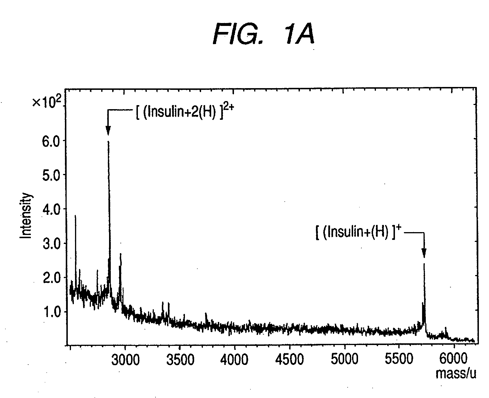
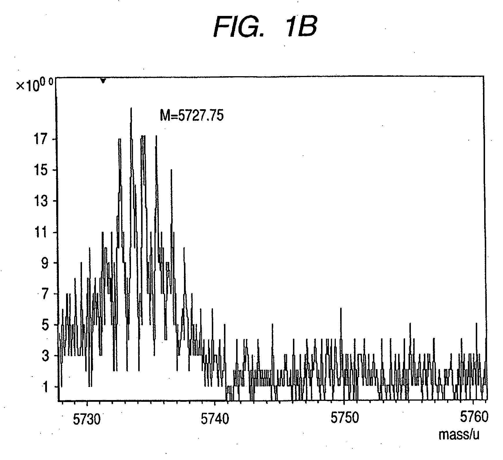
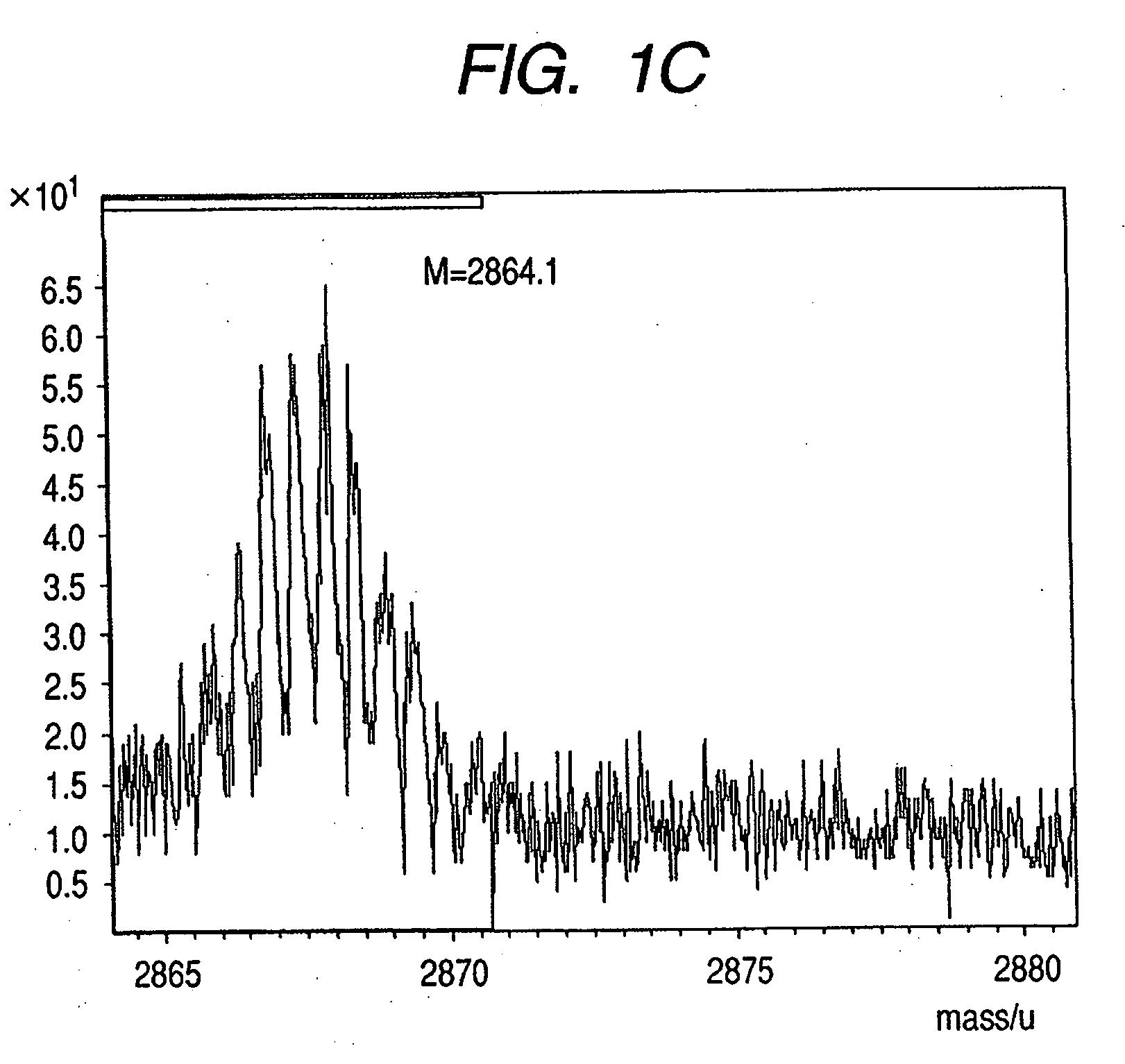
[0054] As a substrate, there was used a substrate obtained by washing a silicon (Si) substrate containing no impurities with acetone and deionized water in that order and forming a film (100 nm) thereon with gold (Au). A 10 μM aqueous solution of bovine insulin (C254H377N65O75S6 (the average molecular weight: 5729.60, the mass of a molecule including elements having a highest isotope abundance: 5733.57), hereinafter referred to as insulin) purchased from Sigma Corporation was prepared with deionized water. The aqueous solution was spotted onto the aforementioned Au-coated Si substrate using a micropipetter. The thus-prepared substrate was air-dried, and then a 0.1 mass % trifluoroacetic acid (TFA) aqueous solution was spotted again onto the position where the insulin aqueous solution had been spotted using a micropipetter. The substrate was air-dried and then used for a TOF-SIMS analysis. In the TO...


PUM


Abstract

In-plane distribution of a target objectcontained in a sample is measured. The sample dispersedly placed on a substrate is treated to promote ionization of the target object, then the mass and flying amount of an ion containing the target object or a component of the target object is determined by irradiating an ion beam to the sample and performing time-of-flight secondary ion mass spectrometry of the ion that flies from a portion in the sample where the ion beam is irradiated, and the in-plane distribution of the target object is determined from the mass and flying amount data obtained at plural portions by scanning the beam on the sample plane. The step of treating the sample to promote ionization of the target object includes contacting an aqueous solution of an acid that does not crystallize at ordinary temperature with the sample. A high spatial resolution two-dimensional image can be obtained.

Description

BACKGROUND OF THE INVENTION [0001] 1. Field of the Invention [0002] The present invention relates to a method of acquiring information of a target object using a time-of-flight secondary ion mass spectrometer and to an imaging detection method by type of a constituent of the target object, in particular, an organic substance such as a protein. [0003] 2. Related Background Art [0004] With the developments in recent genomic analyses, there has become important an analysis of proteins which are gene products that exist in a living body, in particular, a protein tip or a technology for visualizing a distributed protein that are present in, e.g., a living tissue. [0005] Conventionally, the importance of analyses of protein expressions and functions has been indicated, and development of the analysis means is proceeding. Basically, the means have been performed by combining: [0006] (1) separation and purification by two-dimensional electrophoresis or high-performance liquid chromatography...

Claims


Application Information

Patent Timeline
IPC IPC(8): H01J49/00
CPCH01J49/0004Y10T436/24H01J49/40
Inventor MURAYAMA, YOHEIKOMATSU, MANABUHASHIMOTO, HIROYUKI
Owner CANON KK
Why Eureka
Try Eureka