Information display system, display device, display device drive method and display apparatus

Inactive Publication Date: 2006-06-15
FUJITSU LTD
View PDF24 Cites 63 Cited by
  • Summary
  • Abstract
  • Description
  • Claims
  • Application Information

AI Technical Summary

Benefits of technology

[0035] A DDS (dynamic drive scheme) method disclosed by the patent document 10, et cetera, while giving a high speed scan, describes a complex drive wave form which complicates its drive circuit and hence increases cost. Furthermore, a long elapsed time before the display state of pixels settles itself (i.e., reset period to holding period) is so lo

Problems solved by technology

This method naturally precludes a single view of the whole image at once, requiring operations such as cumbersome scrolling.
Such enlarged display methods are not suitable for mobile equipment in mobile environments such as away from the office or home, since they require either an AC power supply or some kind of battery, and such apparatuses per se are heavy.
Such a method, however, is disadvantageous since it is an electrical contact connection.
Equipping the display unit with a battery not only causes the inconvenience of changing the battery for the display unit or charging the battery, but also an increase in the thickness and/or weight of the display.
Battery operation mobile printer apparatuses are commercially available for meeting such a requirement, which are faced with problems such as the weight and size of such equipment as well as supply of paper or batteries, however.
However, there has conventionally been no well designed convenient display system linking to a mobile terminal by using a noncontact wireless technique which has actually been retarded for technical reasons, e.g., shortage of power required for recording voltage, memory retention capability and recording speed for example, hence failing to accomplish a display on a noncontact mobile terminal to date.
Therefore, it is very difficult to use the technique for non-powered recording.
Electrochromic memory is a memory storage method utilizing a chemical reaction and requiring a large amount of power for recording, and hence is difficult to use in wireless recording.
Meanwhile, with regards to a memory capable LC, a ferroelectric memory liquid crystal medium, while rendering high-speed recording, is faced with the problems of inadequate brightness in a reflective white display due to the use of polarization film and loss of display due to physical shock.
This material, utilizing light scattering, has been faced with the problems of being limited to low contrast and requiring a bias voltage for holding a display stable.
This structure, however, having many interfaces producing a lot of optical noise, suffers a reduced display contrast.
There is also the problem of having many components, resulting in a high cost apparatus.
There is a capsule structure for sealing an LC within a capsule as a method for separating LCs, which has been faced with the problems of reduced contrast due to optical noise and an increased drive voltage, both influenced by the interface and thickness of the capsule, hence its use is disadvantageous in a display apparatus, and the difficulty in laying desired capsules for desired pixels.
Consequently high cost of the power supply circuit has been an issue.
Furthermore, the use of a common DC-DC converter requires a large capacitance capacitor (in the order of micro Farads), resulting in bringing forth a problem of extreme difficulty in designing the power supply circuit within a thickness of one millimeter.
For a commercially available STN LCD driver LSI, the requirement is five different voltages for example, bringing forth the problem of a high cost power supply circuit.
This has brought forth a problem of shortening the communicable distance as compared to common noncontact IC cards without a display unit or temporary shortage of power requ

Method used


Image

  • Information display system, display device, display device drive method and display apparatus
  • Information display system, display device, display device drive method and display apparatus
  • Information display system, display device, display device drive method and display apparatus

Examples


first embodiment

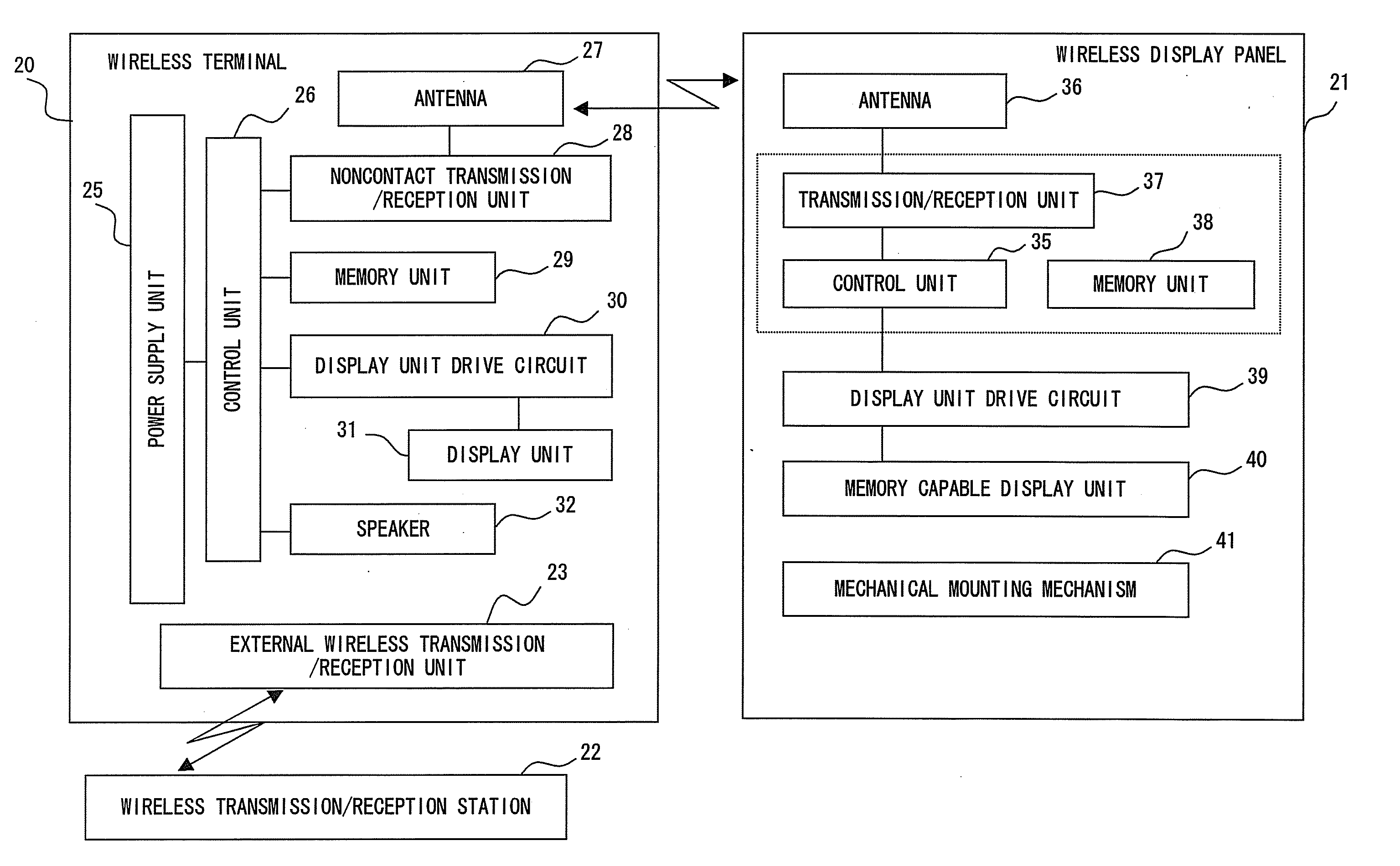
[0162] Preferred embodiments of the present invention will now be described by categorizing them into some embodiments in the following. To begin with, the description will deal with a first embodiment, that is, an information display system for carrying out display on the display apparatus side by using power transmitted from a wireless terminal side, such as a noncontact IC card, along with data, while an information display apparatus, that is, a display panel has no power.

[0163]FIG. 7 is a block diagram showing a comprisal of a first example of such an information display system. In FIG. 7, the display system comprises a wireless terminal 20 and a wireless display panel 21. And the wireless terminal 20 comprises an external wireless transmission / reception unit 23 and is enabled to exchange external wireless information with a wireless transmission / reception terminal station 22. The external wireless transmission / reception unit 23 can be a wireless LAN transmission / reception unit....

second embodiment

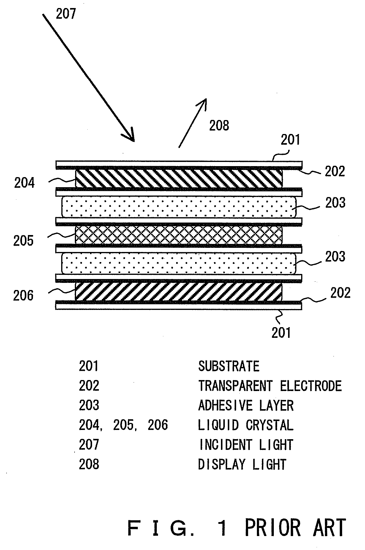
[0185] What follows here is the description of a cholesteric LCD device as a representative display medium capable of continuing display in a state of the power supply being cut off and a display apparatus using the display device as the present invention.

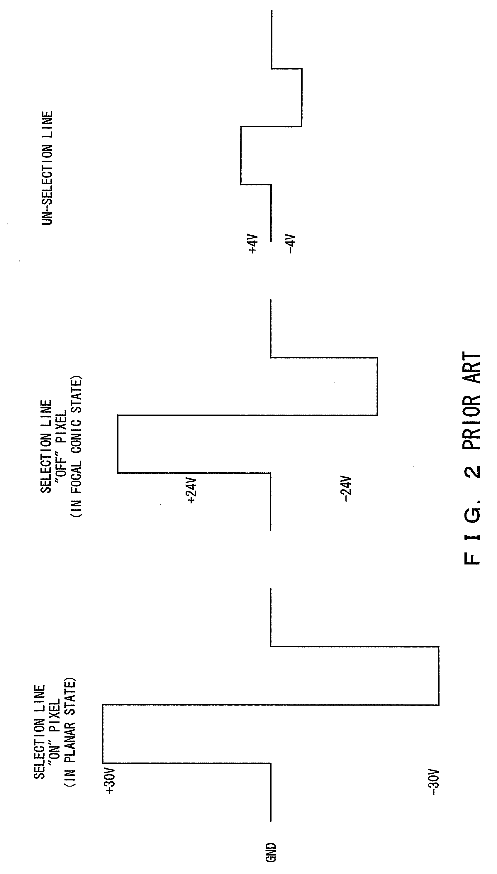
[0186] First, let a characteristic of the cholesteric LC be described in general terms. The cholesteric LC has a property of reflecting light in a certain wavelength range selectively; among such materials chiral-nematic LC is the result of nematic LC forming a cholesteric phase by adding a chiral material thereto. The cholesteric LC provides two stable states, i.e., the planar state as a reflective state and the focal conic state as a transmissive state, by electrical control, having the characteristic of memory property in holding the planar and focal conic states, respectively, semi-permanently unless a certain kind of external force is applied.

[0187]FIGS. 20 and 21 describe the planar state and the focal conic state, respectiv...

third embodiment

[0222] Accordingly, the third embodiment is configured to use a power supply circuit for generating a high voltage of about 40 volts by an ultra-thin circuit through utilizing a high frequency magnetic field used to supply a signal and power for a noncontact IC card or RF tag, instead of using a DC / DC converter.

[0223]FIG. 43 exemplifies such a power supply circuit, which works as the power supply for display such as power for logic use by an LCD driver and the power supply for the display device per se, that is, for display power required by the cholesteric LC.

[0224] The configuration shown by FIG. 43 provides an intermediate tap T in a coil which, having an inductance L, produces a voltage induced by a high frequency magnetic field from a noncontact IC card for example, grounds one end of the coil, connects a capacitor C1 for resonance between the intermediary tap T and the ground, supplies a voltage for logic by way of a half-wave rectifier, and supplies a voltage for display thr...


PUM


Abstract

A display apparatus comprises a display unit capable of continuing a display even after the power is shut off, a short range communication unit for receiving display data provided externally and a display control unit for the received data, while an information display apparatus comprises a storage unit for storing display data and a communication unit for transmitting the display data over to the display apparatus, and further the information display apparatus comprises a mechanical quick release mechanism for mounting the display apparatus onto the own apparatus for example, in order to configure a system, which is capable of detachable attachment, between the display apparatus having no power supply and the information display apparatus, such as a wireless terminal, which sends display data and power to the display apparatus.

Description

CROSS-REFERENCE TO RELATED APPLICATIONS [0001] This application is a continuation of PCT application No. PCT / JP2003 / 011314, which was filed on Sep. 4, 2003.BACKGROUND OF THE INVENTION [0002] 1. Field of the Invention [0003] The present invention relates to an information display system comprising mobile equipment for example and an apparatus for displaying discretionary data provided by such equipment, a display device, display device drive method and display apparatus used for such an information apparatus, and specifically to a system comprising a wireless terminal for example and a noncontact IC card, a display device and its drive method using a cholesteric liquid crystal, et cetera, capable of retaining a display even if electric power (NB simply “power” hereinafter unless otherwise noted) is cut off, and a display apparatus using electronic paper with such a memory property for example. [0004] 2. Description of the Related Art [0005] There is a requirement of enlarged display ...

Claims


Application Information

Patent Timeline
IPC IPC(8): C09K19/52G02F1/13G02F1/133G02F1/1333G02F1/137G09G3/20G09G3/36
CPCG02F1/133377G02F1/13718G02F2203/34G06F3/147G09G3/3651G09G3/3696G09G2300/026G09G2300/0456G09G2300/0486G09G2310/0205G09G2310/08G09G2320/041G09G2340/0457G09G2380/06H04N1/00307H04N1/00342H04N1/00885H04N1/00891H04N1/00893H04N1/00901H04N2201/0084H04N2201/0089H04N2201/0096G09G3/3674H04B1/40G02F1/13G09G3/36
Inventor SHINGAI, TOMOHISATOMITA, JUNJINOSE, MASAKIYAMAGISHI, FUMIO
Owner FUJITSU LTD
Why Eureka
Try Eureka