Modified conductive polymer and conductive member using the same

a technology of conductive polymer and conductive member, which is applied in the direction of non-metal conductors, conductors, organic conductors, etc., can solve the problems of difficult control of the electrical resistance to the required value or uniformity, difficult control of the electrical resistance to the required value, and easy to affect the effect of moistur

Inactive Publication Date: 2006-06-15
THE YOKOHAMA RUBBER CO LTD
View PDF2 Cites 1 Cited by
  • Summary
  • Abstract
  • Description
  • Claims
  • Application Information

AI Technical Summary

Benefits of technology

[0009] By modifying the conductive polymer by chemical treatment with a radical species according to the present invention, it is possible to uniformly disperse the conductive polymer in an organic polymer and possible to obtain an organic polymer composition and conductive member having stable electrical characteristics.

Problems solved by technology

In organic polymer compositions containing conductive fillers such as carbon black dispersed in organic polymers, since it is difficult to uniformly disperse the conductive filler in the organic polymer, it has been difficult to control the electrical resistance of the organic polymer composition to a required value or to make it uniform in the composition.
On the other hand, conductive agents such as ion conductive agents, ion conductive resins can be uniformly dispersed in an organic polymer, and therefore, the variation of the electrical resistance can be suppressed and made uniform, but there is the defect that control of the electrical resistance to the required value is difficult.
Further, the electrical resistance is susceptible to the effects of moisture etc.
Thus, there is a defect that an environmental dependency in the electrical resistance is exhibited.
The process is therefore complicated and it is difficult to uniformly treat the composition to make it conductive.
Control of the electrical resistance is difficult.
Further, when dispersing a conductive polymer in the conductive state in an organic polymer, the solubility between the organic polymer and the conducting polymer is not necessarily high, and therefore, the conducting polymer cannot be uniformly dispersed in the organic polymer.
Therefore, there were the problems that the variation in the electrical resistance of the organic polymer composition becomes large and control of the resistance value is difficult (see Japanese Patent Publication (Kokai) No. 2004-277455A and Japanese Patent Publication (Kokai) No. 2004-205617A)

Method used


Image

  • Modified conductive polymer and conductive member using the same
  • Modified conductive polymer and conductive member using the same
  • Modified conductive polymer and conductive member using the same

Examples


reaction example 1

Preparation of Conductive Polyaniline Dispersion

[0035] 6 g of aniline and 21 g of dodecyl benzene sulfonate were dissolved in 300 g of toluene, then 100 g of distilled water containing 10.8 ml of hydrochloric acid having a concentration of 6 ml / liter dissolved therein was added. This mixed solution was cooled to 5° C. or less, then 100 g of distilled water containing 16.2 g of ammonium persulfate dissolved therein was added. This solution was oxidatively polymerized under conditions of 5° C. or less for 7 hours, then 450 g of toluene was added to the reaction solution. Further, a mixed solution containing 150 g of water, in which 80 g of methanol was dissolved, was added and stirred. When the stirring was stopped and the reaction solution allowed to stand, the reaction solution separated into the two layers of a toluene layer and a water-methanol layer. The toluene layer, in which the conductive polyaniline was dispersed, was recovered.

Reaction Example 2 Preparation of Chemically ...

reaction example 3

Preparation of Chemically Treated Modified Conductive Polyaniline Dispersion 2

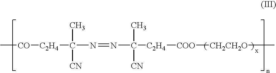
[0037] 20 g of an NMP solution containing 0.7 g of a polymer-based azo compound VPE-201 (made by Wako Pure Chemical Industries) was added to 80 g of a conductive polyaniline dispersion obtained in Reaction Example 1. The solution was reacted under nitrogen at 70° C. for 16 hours, then the toluene was removed by heating under vacuum to obtain an NMP dispersion 2 of a chemically treated modified conductive polyaniline (3% by weight of polyaniline content). Part of the modified conductive polyaniline NMP dispersion was recovered and the NMP was removed by heating under vacuum to obtain a green powder. This powder was treated by aqueous ammonia, then was washed with water and dried to obtain an undoped polyaniline powder. The infrared absorption spectrum of this powder exhibited absorption derived from polyether chains near 1100 cm−1, and therefore, it was confirmed that the conductive polyaniline was chemica...

reaction example 4

Preparation of Chemically Treated Modified Conductive Polyaniline Dispersion 3

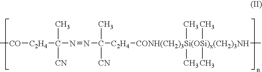
[0038] 0.7 g of the polymer-based azo compound VPS-501 (made by Wako Pure Chemical Industries) was added to 80 g of a conductive polyaniline dispersion obtained in Reaction Example 1. The dissolution of the starting agent was confirmed, then 20 g of NMP was added and the resultant mixture reacted under nitrogen at 70° C. for 16 hours to thereby obtain an NMP dispersion 3 of a chemically treated modified conductive polyaniline (3% by weight of polyaniline content). A part of the modified conductive polyaniline NMP dispersion was recovered and the NMP was removed by heating under vacuum to obtain a green powder. This powder was treated with aqueous ammonia, then was washed with water and dried to obtain an undoped polyaniline powder. The infrared absorption spectrum of this powder exhibited absorption derived from siloxane bonds near 1000 cm−1, and therefore it was confirmed that the conductive polyaniline ...


PUM

PropertyMeasurementUnit
temperatureaaaaaaaaaa
volume resistivityaaaaaaaaaa

Abstract

A modified conductive polymer containing a conducting polymer chemically treated with a radical species, whereby an organic polymer composition having small variation in electrical resistance value and environmental dependency and exhibiting stable electrical characteristics and a conductive member using the same are provided.

Description

BACKGROUND OF THE INVENTION [0001] 1. Field of Invention [0002] The present invention relates to a modified conductive polymer chemically treated with a radical species and an organic polymer composition containing the same and to a conductive member using the composition. This conductive member is useful as a conductive member such as a transfer roll, charge-carrying roller, transfer belt of an electronic photo recording apparatus such as a copier, color printer. [0003] 2. Description of the Related Art [0004] Conductive agents are formulated into organic polymers for the purpose of imparting conductivity to the organic polymers. As such conductive agents, conductive fillers such as carbon black, metal oxide fine particles, are used. In organic polymer compositions containing conductive fillers such as carbon black dispersed in organic polymers, since it is difficult to uniformly disperse the conductive filler in the organic polymer, it has been difficult to control the electrical ...

Claims


Application Information

Patent Timeline
Patent Type & Authority Applications(United States)
IPC IPC(8): H01B1/12
CPCC08G61/124C08G61/126C08K5/0075C08L33/06C08L65/00C08L79/08C09D165/00H01B1/127H01B1/128
Inventor MARUYAMA, TSUKASASEKINE, YUKO
Owner THE YOKOHAMA RUBBER CO LTD
Why Eureka
Try Eureka