Process and apparatus for preparing a diamond substance

a diamond and process technology, applied in the field of composite diamonds, can solve the problems of poor quality at the periphery, inhomogeneous product formation, and substantially good quality

Inactive Publication Date: 2006-06-15
WOJAK GREGORY J
View PDF33 Cites 41 Cited by
  • Summary
  • Abstract
  • Description
  • Claims
  • Application Information

AI Technical Summary

Benefits of technology

[0034] As such, those skilled in the art will appreciate that the conception, upon which this disclosure is based, may readily be utilized as a basis for the designing of other structures, methods and systems for carrying out the several purposes of the present invention. It is to be understood that the aforementioned description is illustrative only and that changes can be made in the apparatus, in the ingredients and their proportions, and in the sequence of combinations and process steps, as well as in other aspects of the invention discussed herein, without departing from the scope of the invention as defined in the fo

Problems solved by technology

One significant disadvantage of the combustion torch process is that an inhomogeneous product is formed, having substantially good quality near the center of the flame and poor quality at is periphery.
The diamond substances produced deposit non-uniformly along the surface, concentrating in certain areas and thus requiring a grinding step to obtain the flat surfaces desired by many users.
This grinding step is inefficient, wasting expensive product and raw materials, as well as requiring additional process steps, labor, energy, equipment and material.
Prior art processes are unable to coat diamond substances on large target materials because they are limited by the area covered by the active plasma.
Plasmas covering large areas tend to be unstable and difficult to control.
This instability causes large inhomogeneities in both the quantity and quality of the deposit, which result in a final product of insufficient quality for most applications.
Such electrical or electromagnetic sources of energy couple inefficiently wi

Method used


Image

  • Process and apparatus for preparing a diamond substance
  • Process and apparatus for preparing a diamond substance
  • Process and apparatus for preparing a diamond substance

Examples


example 1

[0217] A diamond deposition system was built using the following equipment and methods: A set of two Uniweld Products “All Trades II” V style Oxyacetylene outfits were employed, each of which consisted of a pair of hoses, an oxygen regulator, an acetylene regulator, a torch handle with internal gas mixing, and a set of welding tips ranging in size from 0 to 10; also utilized were four Aera FC-980 mass flow controllers, four DP 455C digital panel meters, four 3610C control potentiometers, and an Aera AS-60A water vapor delivery system, a copper block 6″×6″×1″ with an internal channel and a threaded input and output fitting for water-cooling, an Omega products SAT-12 platinum-rhodium 30 AWG thermocouple (ANSI type S) with an Al2O3 ceramic protection tube, a Keithley Instruments Model 2182 Nanovoltmeter, and a Keithley Instruments Model 248 High voltage power supply.

[0218] The Uniweld torch handle / mixer was attached to a tabletop clamp arm so that the welding tip was positioned above ...

example 2

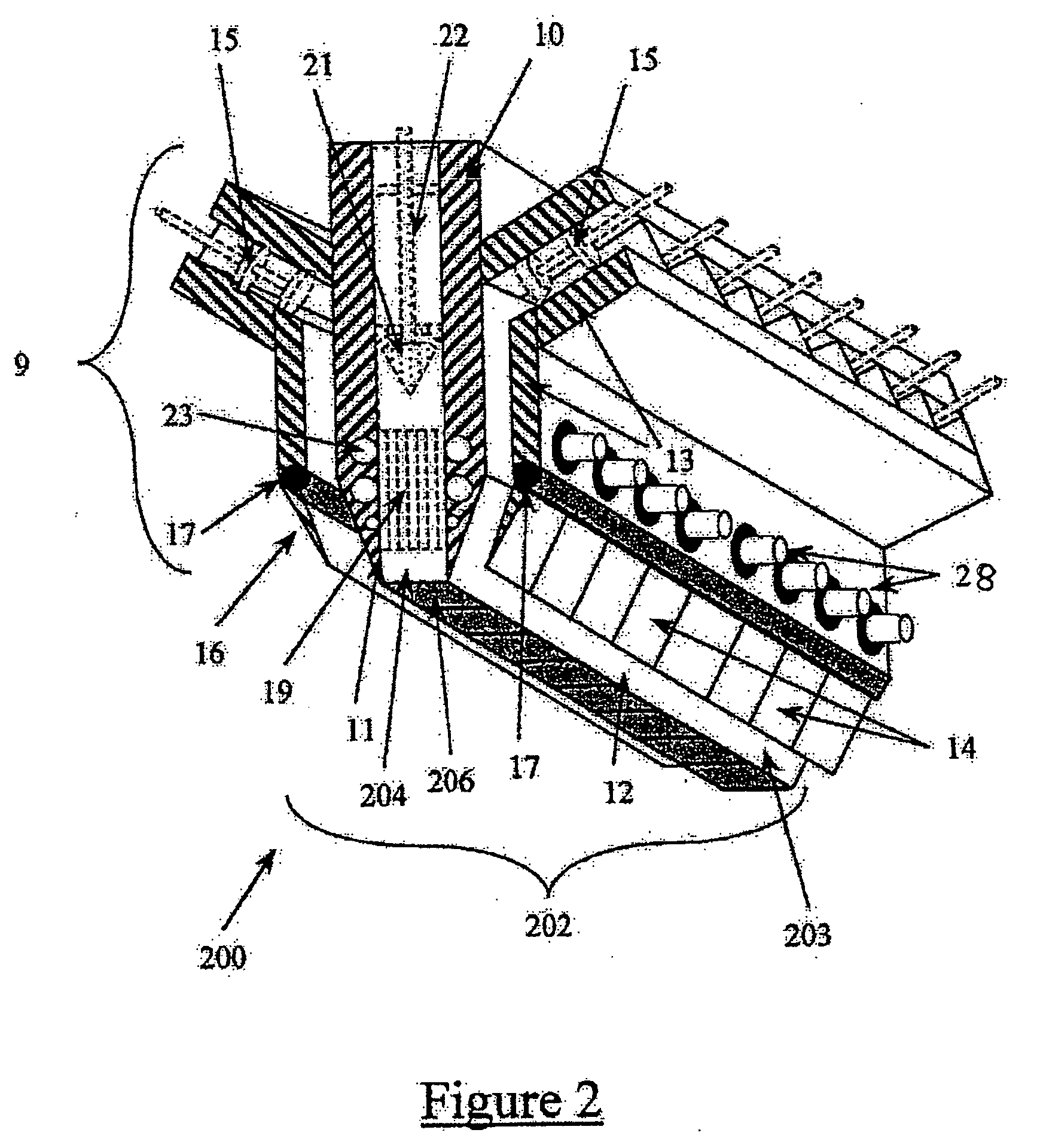
[0221] In accordance with the procedure described for Example 1, another experiment was performed using substantially the same conditions as Example 1 with the following conditions: (a) two welding tips from the Uniweld Products “All Trades II” V style Oxyacetylene torch set were connected to the original welding tip with a set of clamps, (b) these tips were placed parallel to the original, but on opposite sides so that they were 180 degrees apart with the original tip in the center, (c) the ends of the tip were recessed 1 mm from the end of the original tip, (d) the tips were size #6 with an opening diameter of approximately 2 millimeters, (e) the input sides of the tips were connected using brass tubing to two sides of a Y-connector, and the remaining end of the Y-connector was connected to the output port of a Uniweld Products torch handle with internal gas mixing, (f) one of the input ports of the torch handle / mixer was connected directly via a hose and adapter to an Aera FC-980...

example 3

[0226] Another experiment was performed using substantially the same conditions those described in Example 1 with the following differences:

[0227] Three aluminum silicate ceramic pipes 3 inches long and ½ inch in diameter were obtained. The ends of these pipes were machined with a standard sized threading. The ends of these pipes were then fitted with stainless steel adapters and threads were sealed with an epoxy compound. These pipes were then connected between the welding torch tips and the torch handle / mixer. These pipes served to electrically insulate the torch tips from the remaining equipment and ground. The tabletop clamp arm was then readjusted so the position of the torch tip was the same as that described in Example 1.

[0228] A Keithley Instruments Model 248 High voltage power supply was connected between the tip and the substrate. The positive terminal was connected to the torch tip by clamping a copper wire with the sheath removed from the last 8″ to the input side of t...


PUM

PropertyMeasurementUnit
Fractionaaaaaaaaaa
Angleaaaaaaaaaa
Percent by volumeaaaaaaaaaa

Abstract

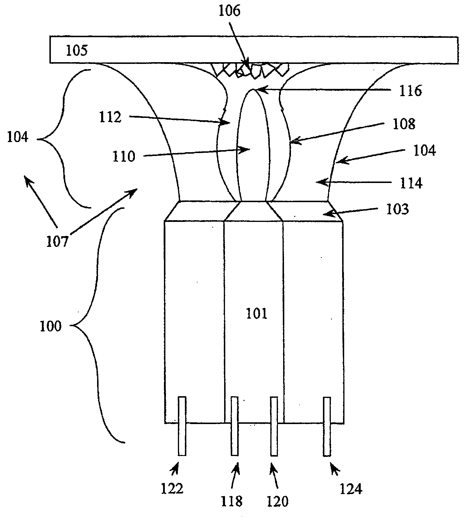
Disclosed in this specification is a process and apparatus for producing a diamond substance. A first mixture comprised of oxygen and a hydrocarbon gas is formed in the first inner nozzle. The first mixture is ignited to produce a flame core. A second mixture comprised of hydrogen and oxygen is formed in an outer nozzle; the second mixture is ignited to produce a flame sheath. The flame sheath is disposed around the flame core so that the flame sheath surrounds the flame core and shields the flame core from the ambient atmosphere; thereby producing a composite flame; and the composite flame is contacted with a substrate.

Description

CROSS-REFERENCE TO RELATED PATENT APPLICATION [0001] This application is a continuation-in-part of applicants' co-pending patent application U.S. Ser. No. 10 / 364,863 (filed on Feb. 11, 2003), priority for which was based upon applicant's provisional application U.S. Ser. No. 60 / 356,304, filed on Feb. 12, 2002. The content of each of the aforementioned patents and patent applications is hereby incorporated by reference into this specification.FIELD OF THE INVENTION [0002] A composite diamond substrate comprised of a diamond substance coated with a thin film, a process and apparatus for producing such diamond substance in which a composite flame comprised of a core of hydrocarbon and oxygen and sheath of hydrogen, oxygen, and water deposits diamond onto a substrate and thereafter coating such diamond substance with a thin film layer comprising an adhesion layer, diffusion barrier layer, thermal barrier layer, chemical reactivity barrier layer, oxidation-reduction barrier layer, and co...

Claims


Application Information

Patent Timeline
IPC IPC(8): C01B31/06C23C16/00B01J3/06H05H1/24H01L21/31
CPCC01B31/06C23C16/01C23C16/02C23C16/0272C23C16/275C23C16/303C23C16/453C23C16/45519C23C16/45589C23C16/45595C23C16/52C23C16/545H01L21/02376H01L21/02447H01L21/02458H01L21/02502H01L21/02521H01L21/02546H01L21/0405H01L23/3732H01L2924/0002H01L2924/00C01B32/25C01B32/26
Inventor WOJAK, GREGORY J.
Owner WOJAK GREGORY J
Why Eureka
Try Eureka