Processes for immobilizing radioactive and hazardous wastes

a radioactive and hazardous waste technology, applied in the direction of sustainable waste treatment, nuclear elements, furnaces, etc., can solve the problems of radionuclides, hazardous elements, hazardous compounds, etc., and achieve the effects of reducing the loading of waste oxide in the vitrification process, and increasing the loading of waste oxid

Inactive Publication Date: 2006-06-15
GEOMATRIX SOLUTIONS INC
View PDF34 Cites 15 Cited by
  • Summary
  • Abstract
  • Description
  • Claims
  • Application Information

AI Technical Summary

Benefits of technology

[0111] As described above, the present invention can immobilize radioactive and hazardous wastes more effectively and more efficiently than prior art processes. Specific advantages of the present invention over prior art vitrification processes can be summarized as follows.
[0112] A process of the present invention provides a substantially higher waste oxide loading than prior art vitrification processes. Waste oxide loading is the ratio of the weight of waste oxides to the weight of the final product. The waste loading oxide obtainable using the present invention is at least about 60% by weight (see Example 8), which is significantly greater than the waste oxide loading achieved in prior art vitrification processes. Waste oxide loading in vitrification processes is limited due to the solubility of the waste oxides, and due to the presence of some anions in the waste, such as sulphates, which weaken the properties of the glass. The present invention overcomes these limitations. The present invention is not limited by the solubility of the waste oxides because the oxides are immobilized within the immobilizing mineral. Those oxides which are integrated in the surrounding rock or glass matrix are not dissolved in the present invention. In an embodiment of the present invention, sulphate is also integrated into the immobilizing mineral, thereby inhibiting the weakness of the glass.
[0113] The process of the present invention can be carried out in the same or shorter amount of time than existing vitrification processes. As mentioned above, the process of the present invention can achieve higher waste oxide loading than existing vitrification processes. This means that the present invention can immobilize the same amount of waste in substantially less time than it would take using the prior art vitrification process. It also means that, for a given amount of waste, the final product of the present invention occupies substantially less volume than the final product of the prior art vitrification process, which means the final product of the present invention can result in significant cost savings associated with final disposal.
[0114] The present invention utilizes minerals to immobilize radioactive or hazardous wastes. Minerals provide a more stable thermodynamic system to withstand environmental conditions than glass that is used in prior art vitrification processes.
[0115] The present invention provides as many as four physicochemical barriers against leaching and diffusion. A first barrier is provided by the integration of radionuclides with the immobilizing mineral to create a waste integrated mineral in which the radionuclides, hazardous elements, and / or hazardous compounds are strongly bonded to other elements of the immobilizing mineral. Microprobe analyses of the of the product of the present invention demonstrates that the radionuclides are integrated with the immobilizing mineral.
[0116] A second barrier is created by the physicochemical method of covering of the immobilizing mineral by a non-radioactive and non-hazardous mineral layer, which effectively inhibits both leaching and diffusion of radionuclides from the immobilizing mineral. The second barrier can be created by an overgrowth procedure or by sintering. A 20-micron covering created by an overgrowth procedure can offer protection for approximately 200,000 years. A 50-micron covering attainable by the present invention offers protection for approximately one million years. In the case of sintering, the covering formed is a minimum of several millimeters. Therefore, the level of protection attained is at least as much as that offered by a 50-micron overgrowth.

Problems solved by technology

The process of creating this first barrier results in a loading of radionuclides, hazardous elements, hazardous compounds, and / or other compounds found in the waste that is two weight percent or greater.

Method used


Image

  • Processes for immobilizing radioactive and hazardous wastes
  • Processes for immobilizing radioactive and hazardous wastes
  • Processes for immobilizing radioactive and hazardous wastes

Examples


example 1

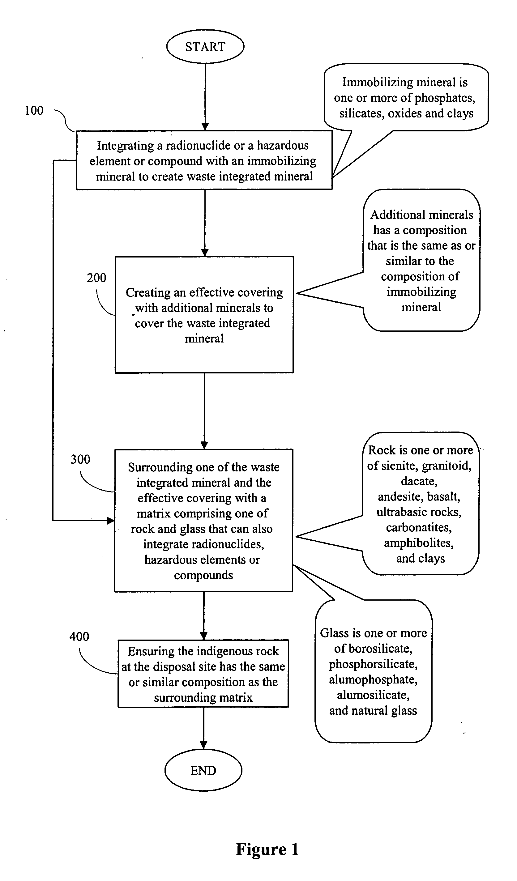
Method for Immobilizing Liquid Form Waste in Natural Minerals

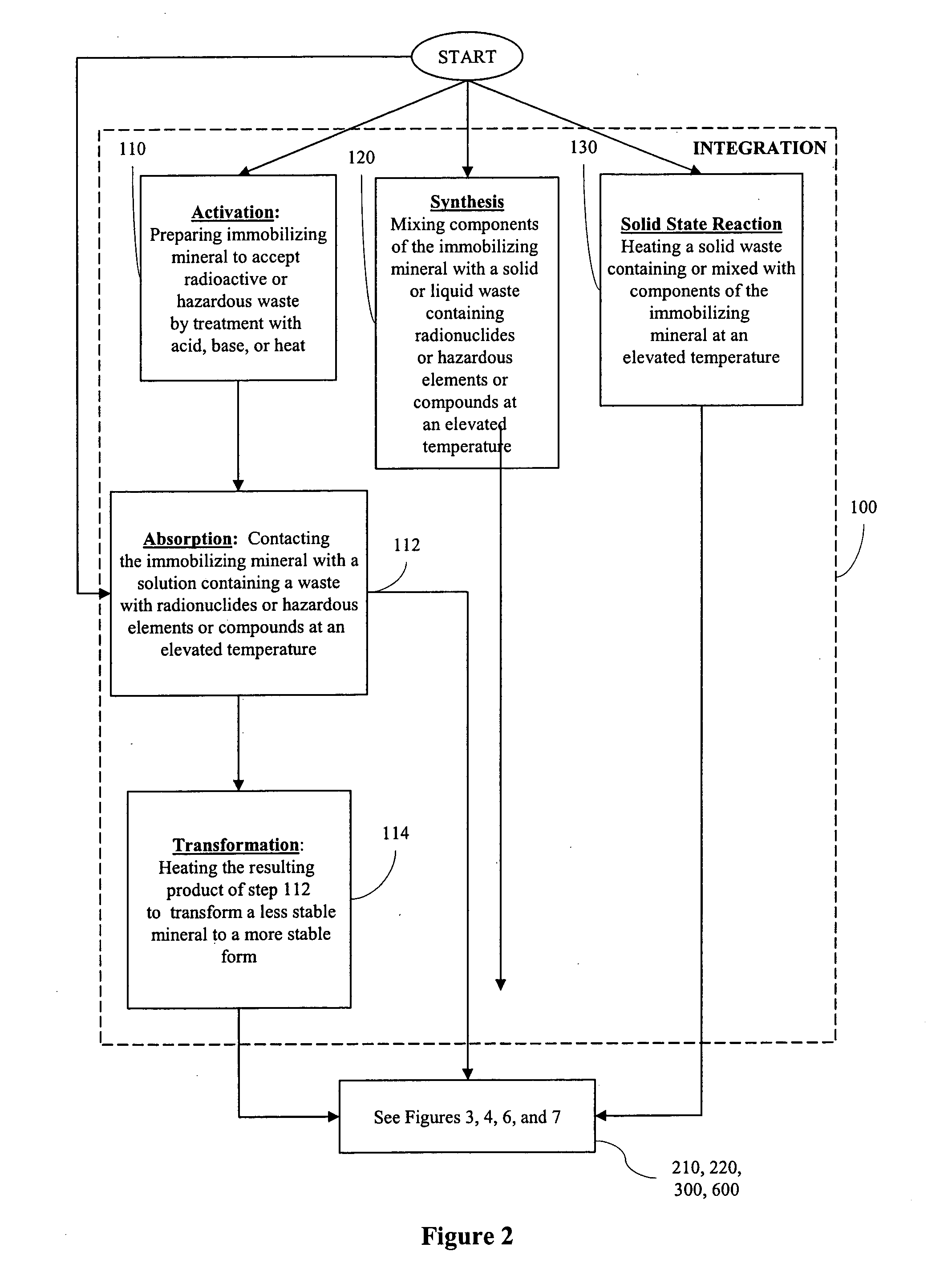
[0130] 1. Activation A natural calcium-zeolite was crushed and heated to about 400° C. for about 12 hours to remove volatile components.

[0131] 2. Absorption Thorium nitrate crystalline hydrate was dissolved in water resulting in an aqueous solution containing thorium. This solution was then stirred with the calcium-zeolite crystals (the crystals had a particle size of less than 300 microns) at room temperature and then dried in a furnace at 110° C. for about two hours.

[0132] 3. Transformation The resulting crystals were then heated for about 12 hours at about 800° C. resulting in the calcium-zeolite being transformed into feldspar containing thorium. The heating was done at the atmospheric pressure in a furnace.

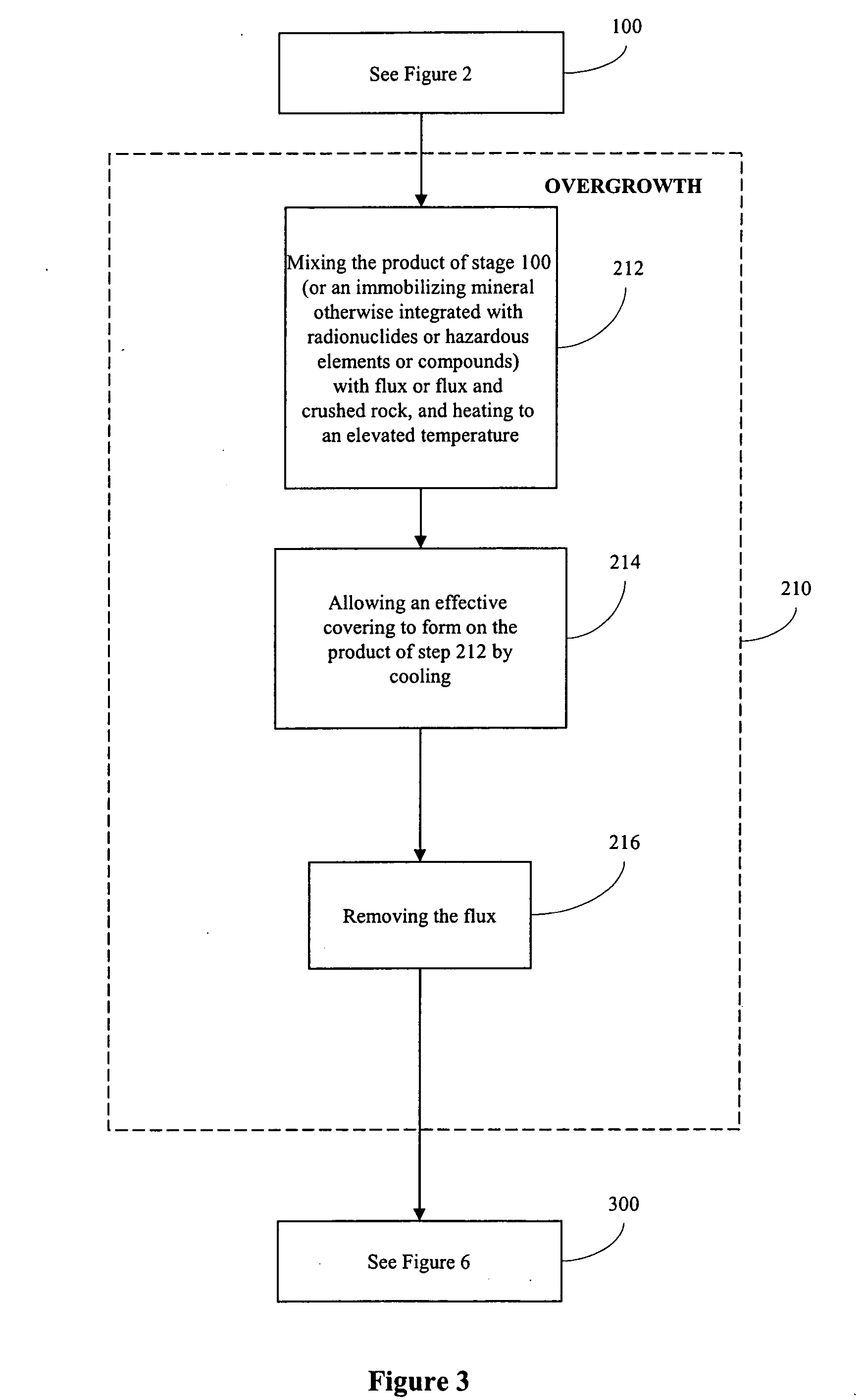
[0133] 4. Overgrowth+Glass Matrix The result was mixed with crushed obsidian and heated at about 1200° C. for several hours and then cooled by gradual decrease in temperature for up to 48 hours until reaching 60...

example 2

Method for Immobilizing Solid Form Waste in Synthesized Minerals

[0137] 1. Synthesis Ce2O3 and NaPO3 and La2O3 (the components of monazite) were taken and about 10% to 15% by weight of the cerium and lanthanum were replaced by uranium and thorium. This was done by heating all of these components together at 1200° C. for about two days at the atmospheric pressure using a furnace. The result was synthesized monazite in which part of the cerium and lanthanum were replaced by uranium and thorium. The synthesized monazite was then quenched outside the furnace.

[0138] 2. Overgrowth with addition of flux The synthesized monazite was then mixed with Na2B4O7.10H2O containing Ce2O3+P2O5. This was then heated at 900° C. for about two days at the atmospheric pressure in the furnace. This was then cooled to room temperature for eight hours by turning off the furnace. This resulted in an overgrowth of the immobilizing mineral. Next, the Na2B4O7.10H2O was dissolved in boiling water, leaving monazi...

example 3

Method for Immobilizing Solid Form Waste in Synthesized Minerals

[0140] 1. Synthesis The synthesis procedure of Example 2 was used.

[0141] 2. Sintering The synthesized monazite containing the uranium and thorium was mixed with natural monazite of the same composition but without uranium and thorium. About 25% by weight of the synthesized monazite was mixed with 75% by weight of the natural monazite using a mortar by hand. This mixture was heated to about 900° C. to 1000° C. at atmospheric pressure in a furnace for about one day and then was cooled by gradual decrease of temperature to room temperature for eight hours. This results in a conglomerate comprising monazite crystals containing uranium and thorium surrounded by monazite crystals without uranium and thorium.

[0142] 3. Sintering a second time Some uranium and thorium crystals may remained on the surface. Approximately 10% by volume of crushed monazite was then added to the conglomerate of crystals and heated to about 900° C....


PUM

PropertyMeasurementUnit
weight %aaaaaaaaaa
thicknessaaaaaaaaaa
thicknessaaaaaaaaaa

Abstract

The present invention utilizes one or more processes to immobilize a waste that contains one or more of radionuclides, hazardous elements, hazardous compounds, and/or other compounds present in the waste. Each of the processes create a barrier against leaching and diffusion of the wastes. The first barrier is created by integrating the waste with an immobilizing mineral. The second barrier is a layer of non-radioactive or non-hazardous material that covers the first barrier. The second barrier may be created using an overgrowth procedure or by sintering. The third barrier is created by a rock or glass matrix that surrounds the first and/or second barriers. The fourth barrier is created by ensuring that the rock or glass has the same or similar composition as the indigenous rock at the disposal site. The resultant rock or glass matrix is in equilibrium with the groundwater or local hydrothermal solutions that are saturated with components of the indigenous rock of the disposal area.

Description

[0001] This application claims the benefits of Israeli Patent Application Serial Number IL 136,685, filed Jun. 12, 2000. BACKGROUND [0002] 1. Field of the Invention [0003] The present invention relates generally to treatment of radioactive and hazardous wastes, and more particularly to processes for immobilizing a waste containing one or more of radionuclides, hazardous elements, hazardous compounds, and other compounds present in the waste. [0004] 2. Background of the Invention [0005] The use of radioactive and hazardous materials in the world has led to the accumulation of a significant amount of radioactive and hazardous wastes. There is an international consensus regarding the planned disposal of these wastes by burying them in the ground in deep geological repositories. At the present time, high-level radioactive wastes are being placed in long-term storage awaiting permanent disposal. Once buried, with the passage of time, groundwater and hydrothermal solutions can make contac...

Claims


Application Information

Patent Timeline
Patent Type & Authority Applications(United States)
IPC IPC(8): G21F9/16A62D3/00B09B3/00C04B18/04G21F9/00G21F9/04G21F9/06G21F9/28G21F9/30
CPCB09B3/0041C04B18/0463G21F9/162G21F9/302G21F9/305Y02W30/91B09B3/25
Inventor CHEKHMIR, ANATOLYGRIBETZ, ARTHUR
Owner GEOMATRIX SOLUTIONS INC
Why Eureka
Try Eureka