Imparting high-temperature degradation resistance to components for internal combustion engine systems

a technology of degradation resistance and internal combustion engine, which is applied in the direction of diffusion coating, solid-state diffusion coating, transportation and packaging, etc., can solve the problems of weak and brittle lavage phases, cumbersome or unfeasible plasma transfer arc welding, and impede the welding process

Active Publication Date: 2006-06-22
KENNAMETAL INC
View PDF25 Cites 31 Cited by
  • Summary
  • Abstract
  • Description
  • Claims
  • Application Information

AI Technical Summary

Benefits of technology

[0012] Briefly, therefore, the invention is directed to a method of imparting high-temperature, degradation resistance to a component associated with an internal combustion engine. The method involves applying a metal slurry comprising a Co-based metallic composition, a binder, and a solvent to a surface of the component; and sintering the Co-based metallic composition to form a substantially continuous Co-based alloy coating on the surface of the body.

Problems solved by technology

Laves phases are strong and brittle, due in part to the complexity of their dislocation glide processes. FIG. 1 is a photomicrograph showing irregularly shaped dendritic Laves phase particles formed by solidification of a Tribaloy® alloy.
With irregularly shaped components, however, plasma transferred arc welding becomes cumbersome or unfeasible.
For example, sharp projections, cavities, and through holes can hinder the welding process by influencing the location at which the plasma arc is transferred to the work piece.
Thermal spraying can sometimes be used to coat irregular surfaces, but it results in only a mechanically bonded coating.
Mechanically bonded coatings are susceptible to spalling caused by thermal cycling.
Thus, the coating can not be applied to surfaces that cannot be reached by the spraying torch.
Actuation of the vanes 22 in this manner results in stress and wear on the pins 26 and the actuation tabs 30.
Although it is desirable to apply a protective high-temperature, degradation-resistant coating to these components, their irregular shapes make this difficult or uneconomical to achieve.
Consequently, many irregularly shaped component parts are made by investment casting with expensive alloys.

Method used


Image

  • Imparting high-temperature degradation resistance to components for internal combustion engine systems
  • Imparting high-temperature degradation resistance to components for internal combustion engine systems
  • Imparting high-temperature degradation resistance to components for internal combustion engine systems

Examples


example 1

[0050] Wear tests were conducted by establishing a wear couple between pins coated according to the method of the invention and solid tiles. The pins were 0.75 inch (2 cms) long and 0.25 inch (0.6 cm) diameter. The tiles were 1.25 inch (3 cms)×1.25 inch (3 cms)×0.25 inch (0.6 cm). A long edge of the pins was applied to the tiles at a force of 14.05 N in a static air furnace at 600° C. The pins were rotated about an axis perpendicular to the tile surface for 60 minutes at a frequency of 1 Hz. Surface roughness (Ra) of the tiles was measured and is an indication of surface damage due to wear. Higher roughness indicates greater material transfer:

Pin / TileTile (Ra)T-400 on 316 ss / Cast T-400Coating / Solid0.07T-800 on 316 ss / Cast T-400Coating / Solid0.07T-400 C on 316 ss / Cast T-400Coating / Solid0.09Cast T-400 / Cast T-400Solid / Solid0.11T-800 on 420 ss / Cast T-400Coating / Solid0.13YSZ / Cast T-400Ceramic / Solid0.14PL-33 / Nitrided 316 ssSolid / Solid0.39Stellite 6B / Stellite 6BSolid / Solid0.73PL-33 / 316Sol...

example 2

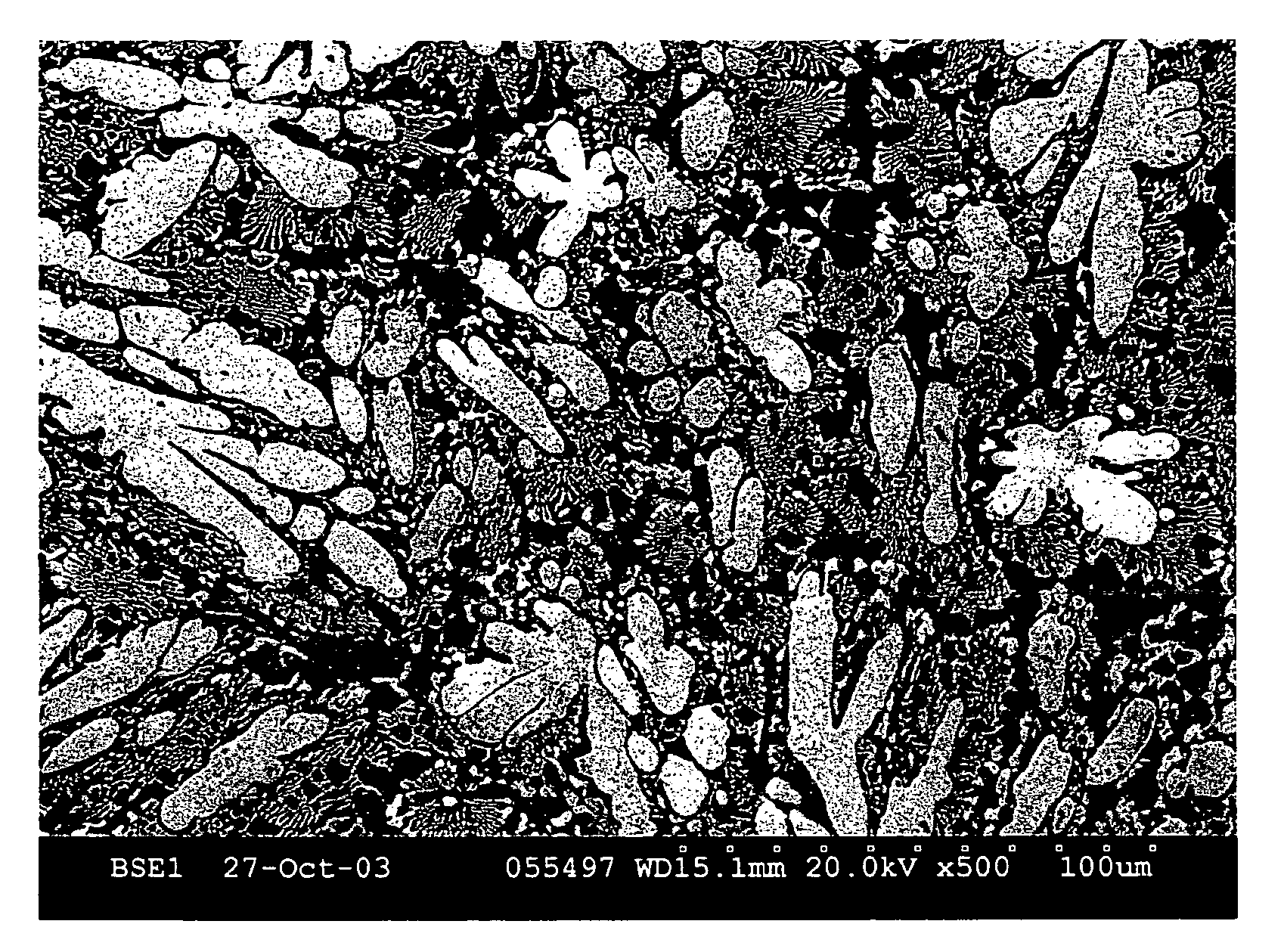
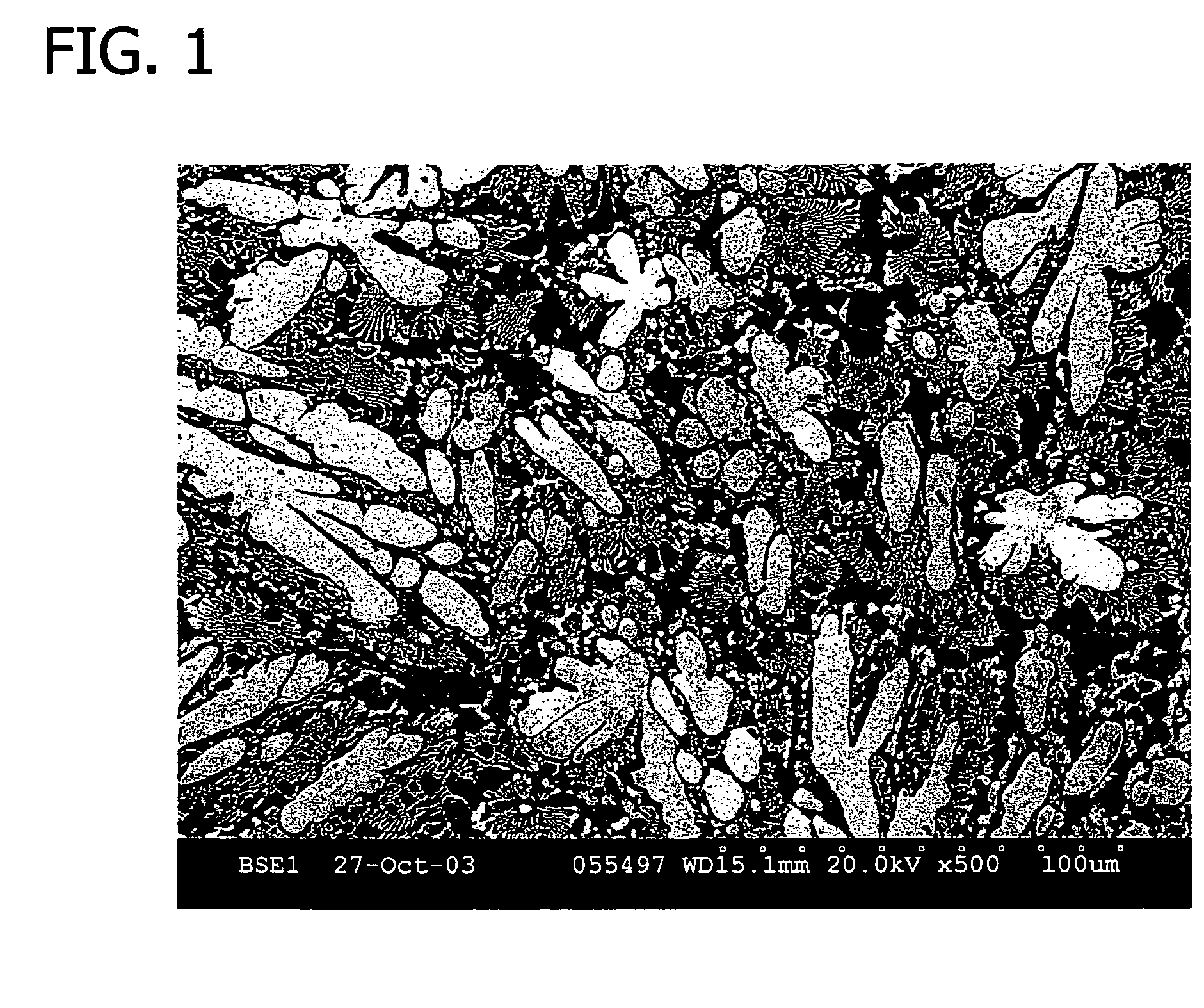
[0052] Back-scattered electron image photomicrographs were taken of a T-800 coating nominally comprising B-0.15%, Cr-17%, Mo-28%, Si-3.25%, and balance Co, and are presented in FIG. 7 (150X) and FIG. 8 (50OX). The substrate was 416 stainless steel. The light particles indicating a high Mo concentration are Laves phase. Advantageously, they are evenly distributed, and there are no elongated or irregularly shaped particles, such as those often observed in castings. In particular, the microstructure, like the microstructure of FIGS. 3 and 4, contains the high-Mo Laves phase which is a generally non-dendritic, irregularly spherical, nodular intermetallic. This microstructure contributes to an improvement in ductility of the T-800 coating of the invention nominally comprising B-0.15%, Cr-17%, Mo-28%, Si-3.25%, and balance Co.

example 3

[0053] Two T-800 coating samples were prepared on a 416 stainless substrate, one according to the coating process of the invention, and the other by HVOF (high velocity oxyfuel) thermal spray coating. The two coatings were the same thickness and were indented under an equal force (hardness tester / 50 kg). The HVOF thermal spray coating exhibited cracking at the indent (FIG. 9), whereas the coating applied according to the method of the invention (FIG. 10) did not, thus demonstrating a significant improvement in ductility.

[0054] When introducing elements of the present invention or the preferred embodiments thereof, the articles “a”, “an”, “the”, and “said” are intended to mean that there are one or more of the elements. The terms “comprising”, “including”, and “having” are intended to be inclusive and mean that there may be additional elements other than the listed elements.

[0055] As various changes could be made in the above products and methods without departing from the scope of...


PUM

PropertyMeasurementUnit
thicknessaaaaaaaaaa
temperaturesaaaaaaaaaa
thickaaaaaaaaaa

Abstract

A method of imparting high-temperature, degradation resistance to a component associated with an internal combustion engine involving applying a metal slurry comprising a Co-based metallic composition, a binder, and a solvent to a surface of the component, and sintering the Co-based metallic composition to form a substantially continuous Co-based alloy coating on the surface of the body. An internal combustion engine component comprising a metallic substrate and a Co-based metallic coating thereon which has a thickness between about 100 and about 1000 microns.

Description

REFERENCE TO RELATED APPLICATION [0001] This application is based on provisional application 60 / 636,398, filed Dec. 15, 2004, the entire disclosure of which is incorporated herein by reference.FIELD OF THE INVENTION [0002] The invention relates generally to high-temperature, degradation-resistant metal parts for use in association with an internal combustion engine and more particularly to a method for imparting high-temperature degradation resistance to an irregularly shaped metal part by coating with a diffusion-bonded cobalt alloy. BACKGROUND [0003] High temperature wear-resistant alloys are often used in the critical parts of internal combustion engines. Certain wear and corrosion resistant cobalt alloys are distributed by Deloro Stellite Company, Inc. under the trade designation Tribaloy®. Alloys within the Tribaloy® alloy family are disclosed in U.S. Pat. Nos. 3,410,732; 3,795,430; 3,839,024; and in pending U.S. application Ser. No. 10 / 250,205. Three specific alloys in the Tri...

Claims


Application Information

Patent Timeline
Patent Type & Authority Applications(United States)
IPC IPC(8): B05D3/02B32B15/00
CPCC22C19/07C23C10/18Y10T428/12861B05D3/0254C23C24/08
Inventor BELHADJHAMIDA, ABDELHAKIMOVERTON, JOSEPHWU, JAMES B. C.
Owner KENNAMETAL INC
Why Eureka
Try Eureka