Separator for fuel cell, method for preparing the same, and fuel cell stack comprising the same

a fuel cell and separator technology, applied in the direction of cell components, final product manufacturing, sustainable manufacturing/processing, etc., can solve the problems of inability to obtain the strength, durability, and stability of the resultant separator composite material at an appropriate level, and achieve excellent anti-corrosion and electro-conductivity characteristics

Inactive Publication Date: 2006-06-22
SAMSUNG SDI CO LTD
View PDF14 Cites 64 Cited by
  • Summary
  • Abstract
  • Description
  • Claims
  • Application Information

AI Technical Summary

Benefits of technology

[0013] An exemplary embodiment of the present invention provides a metal separator for a fuel cell having excellent anti-corrosion and electro-conductivity characteristics.

Problems solved by technology

However, it has problems in the need to carefully handle hydrogen gas and the requirement of accessory facilities such as a fuel reforming processor for reforming methane or methanol, natural gas, and the like in order to produce hydrogen as the fuel gas.
In the prior art, large amounts by weight percent of graphite should be used in order to obtain appropriate electro-conductivity, and processes, such as those using agitating and molding, are difficult because of an increase of the weight and viscosity of the separator materials.
Strength, durability, and stability of the resultant separator composite material cannot be obtained at an appropriate level.
However, a separator made of a metal or an alloy-based material may corrode under carbon monoxide, oxygen, and various acidic atmospheres to form an oxide film resulting in deterioration of the fuel cell performance.

Method used


Image

  • Separator for fuel cell, method for preparing the same, and fuel cell stack comprising the same
  • Separator for fuel cell, method for preparing the same, and fuel cell stack comprising the same
  • Separator for fuel cell, method for preparing the same, and fuel cell stack comprising the same

Examples


example 1

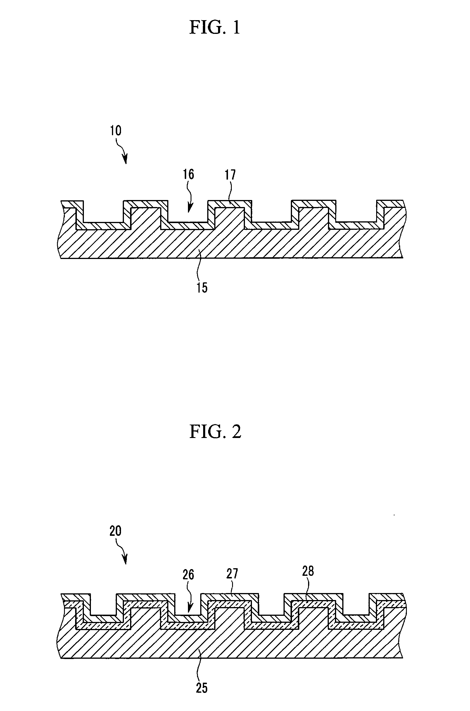
[0071] Metal Separator for a Fuel Cell Including a Tungsten Carbide (WC) Coating Layer

[0072] A metal separator for a fuel cell including a 30 μm thick tungsten carbide (WC) coating layer was prepared by sputtering tungsten carbide (WC) on the surface of a stainless steel (316L) substrate with reactant flow pathways formed thereon.

[0073] A membrane-electrode assembly for a fuel cell was prepared by disposing electrodes including a platinum catalyst at each side of a poly (perfluorosulfonic acid) polymer electrolyte membrane, and then, a fuel cell was fabricated by disposing the metal separators at each side of the membrane-electrode assembly and assembling them.

example 2

[0074] Metal Separator for a Fuel Cell Including a Titanium Carbide (TiC) Coating Layer

[0075] A metal separator for a fuel cell including a 30 μm thick TiC coating layer was prepared by sputtering titanium carbide (TiC) on the surface of a stainless steel (316L) substrate with reactant flow pathways formed thereon.

[0076] A fuel cell was fabricated according to the same method as in Example 1 except that the above metal separator was used.

example 3

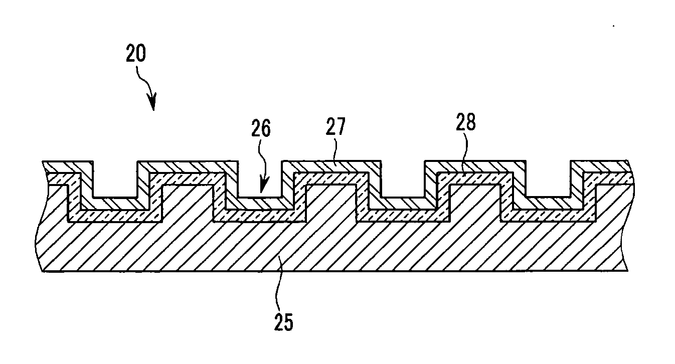
[0077] Metal Separator for a Fuel Cell Including a Zirconium Carbide (ZrC) Coating Layer

[0078] A separator for a fuel cell including a 30 μm thick ZrC coating layer was prepared by sputtering ZrC on the surface of a stainless steel (316L) substrate with reactant flow pathways formed thereon.

[0079] A fuel cell was fabricated according to the same method as in Example 1 except that the above metal separator was used.


PUM

PropertyMeasurementUnit
thicknessaaaaaaaaaa
depthaaaaaaaaaa
depthaaaaaaaaaa

Abstract

The metal separator for a fuel cell of the present invention includes a metal substrate having reactant flow pathways and an electro-conductive anti-corrosion coating layer. The electro-conductive anti-corrosion coating layer covers the surface of the metal substrate on which the reactant flow pathways are formed. The coating layer may include metal carbides, metal oxides, and metal borides. A metal layer for improving adherence is formed between the surface of the metal substrate on which the reactant flow pathways are formed, and the electro-conductive anti-corrosion coating layer.

Description

CROSS-REFERENCES TO RELATED APPLICATION [0001] This application claims priority to and the benefit of Korean Patent Application Nos. 10-2004-0097379, 10-2004-0097380, and 10-2004-0097382 filed in the Korean Intellectual Property Office on Nov. 25, 2004, the entire contents of which are incorporated herein by reference. FIELD OF THE INVENTION [0002] The present invention relates to a metal separator, a method of preparing the same, and a fuel cell stack comprising the same. More particularly, the present invention relates to a lightweight metal separator having excellent anti-corrosion and electro-conductivity characteristics, a method of preparing the same, and a fuel cell stack comprising the same. BACKGROUND OF THE INVENTION [0003] A fuel cell is a power generation system for producing electrical energy through the electrochemical redox reaction of an oxidant and a fuel, such as hydrogen, or a hydrocarbon-based material, such as methanol, ethanol, natural gas, or the like. Such fu...

Claims


Application Information

Patent Timeline
Patent Type & Authority Applications(United States)
IPC IPC(8): H01M8/02B32B15/04B05D5/12
CPCH01M8/0204H01M8/0206H01M8/021H01M8/0215Y10T428/12611H01M8/026H01M2008/1095Y02E60/50Y10T428/12576H01M8/0228Y02P70/50
Inventor LEE, JONG-KIKWEON, HO-JINSUH, JUN-WON
Owner SAMSUNG SDI CO LTD
Why Eureka
Try Eureka