Oscillating shielded cylindrical target assemblies and their methods of use

Inactive Publication Date: 2006-06-29
CARDINAL CG
View PDF14 Cites 21 Cited by
  • Summary
  • Abstract
  • Description
  • Claims
  • Application Information

AI Technical Summary

Benefits of technology

[0013] As previously suggested, embodiments of the cylindrical target of the present invention provide multiple sputtering materials on a single cylindrical target. As a result, the need to change targets or provide multiple cylindrical targets for application of two or more coatings is obviated. This translates into ease of operation and a saving of time and expense when manufacturing substrates containing multiple layers of coating materials.
[0014] Furthermore, the present invention aids in preventing undesirable consumption, co

Problems solved by technology

First, the rotation of the cylindrical target provides for a distributed consumption of the target over a much larger surface area than if the target were to remain stationary.
The deposition and build-up of coating materials upon the surfaces of the target and other surfaces within the system's vacuum chamber cause lost time and increased cost in the clean-up of unwanted sputtering material.
Furthermore, the deposition and build-up of coating material on surface areas of the magnetron sputtering system can result in damage to the various components of the system due to arcing.
Arcing is undesirable since it normally causes an overload to the power supply that creates the plasma, thereby disturbing the generation of plasma causing non-uniform coating, halting production and/or causing damage to equipment.
Finally, overcoating, especially the deposit of oxidized sputtering materials upon a target, such as titanium oxide on a titanium

Method used


Image

  • Oscillating shielded cylindrical target assemblies and their methods of use
  • Oscillating shielded cylindrical target assemblies and their methods of use
  • Oscillating shielded cylindrical target assemblies and their methods of use

Examples


Embodiment Construction

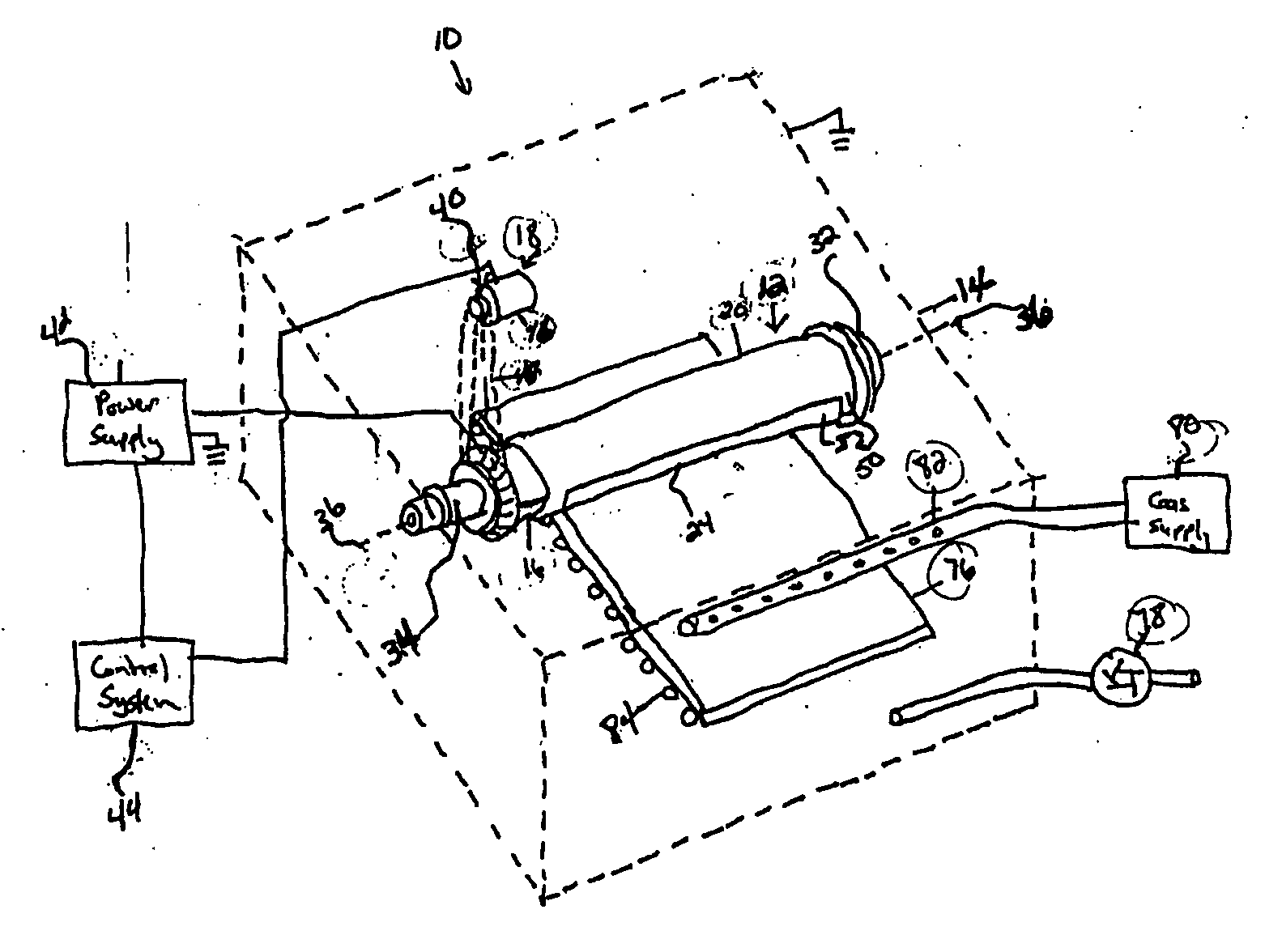
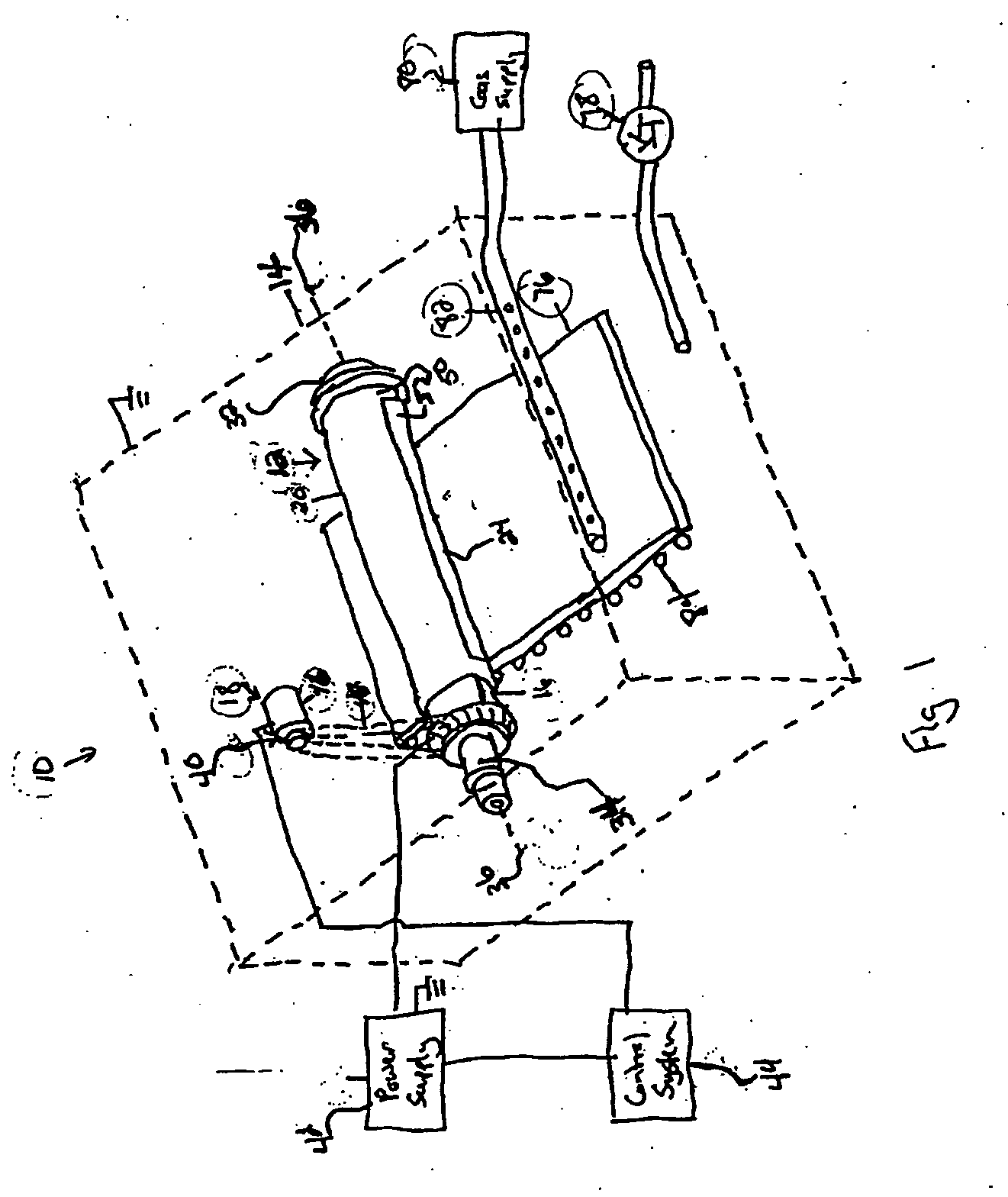
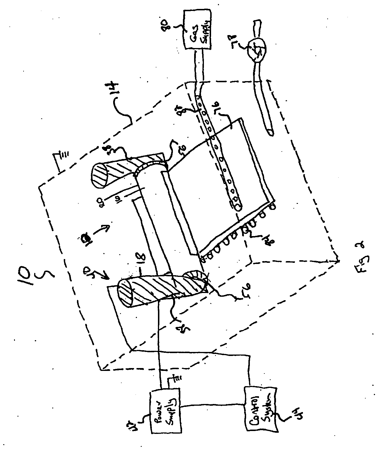
[0029]FIGS. 1-4 depict a magnetron sputtering system 10 that includes embodiments of the oscillating cylindrical target assembly 12 of the present invention. The magnetron sputtering process occurs within a controlled atmosphere vacuum chamber 14, which is depicted in phantom lines in FIGS. 1 and 2. Commonly, the oscillating cylindrical target assembly 12 is positioned within the magnetron sputtering system 10 and comprises a cylindrical target 16, a motor assembly 18, an optional shield assembly 20 and an optional magnet assembly 22 (see FIG. 3).

[0030] Generally, the cylindrical target 16 is a tubular backing tube formed of electrically conductive material, such as stainless steel, aluminum or any other suitably conductive material. The outer surface of the cylindrical target 16 is normally coated with one or more materials, which are intended to be sputtered onto a workpiece or substrate. This coating of sputterable material is also referred to herein as “target material.”

[0031]F...


PUM

PropertyMeasurementUnit
Distanceaaaaaaaaaa

Abstract

The present invention relates to an oscillating shielded cylindrical target assembly comprising a cylindrical target, a motor assembly adapted to oscillate the cylindrical target, a shield, and a magnet assembly. Embodiments of the present invention also include a cylindrical target that has an outer surface containing a plurality of divided sections; the sections being disposed lengthwise around the target to form strips running lengthwise across the target. Each section includes a single sputtering material, such as silver, titanium, or niobium, that is intended to be applied as a separate coating on a substrate, such as glass.

Description

RELATED APPLICATION [0001] The present application claims priority to U.S. provisional patent application 60 / 639,387, filed Dec. 27, 2004, the entire disclosure of which is incorporated herein by reference.FIELD OF THE INVENTION [0002] The present invention relates to an oscillating shielded cylindrical target assembly comprising a cylindrical target, a motor assembly adapted to oscillate the cylindrical target, a shield, and a magnet assembly. Moreover, various embodiments of the present invention relate to an oscillating shielded cylindrical target having a multi-sectional cylindrical target adapted for oscillation. BACKGROUND OF THE INVENTION [0003] Cylindrical targets are widely used in magnetron sputtering systems for depositing thin coatings and films on substrates. A magnetron sputtering process normally is conducted in an evacuated chamber containing a small quantity of an ionizable gas such as argon. A voltage applied to the cylindrical target, with respect to either the va...

Claims


Application Information

Patent Timeline
IPC IPC(8): C23C14/32C23C14/00
CPCC23C14/35H01J37/3405H01J37/3429H01J37/3447H01J37/3455
Inventor HARTIG, KLAUS
Owner CARDINAL CG
Why Eureka
Try Eureka