

Slica fine particles
- Summary
- Abstract
- Description
- Claims
- Application Information
AI Technical Summary
Benefits of technology
Problems solved by technology
Method used
Image

Examples
examples
[0063] The invention will be described more concretely of Examples and Comparative Examples. The invention, however, is not limited in these manners. In the Examples and Comparative Examples, the properties were measured as follows.
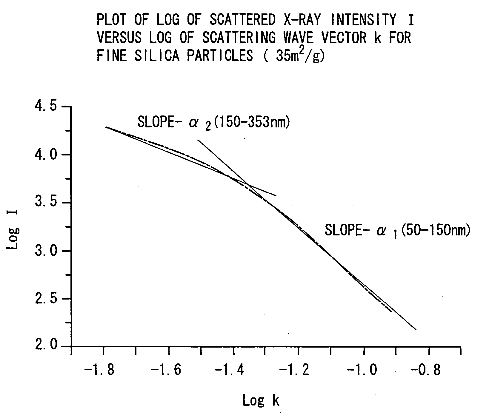
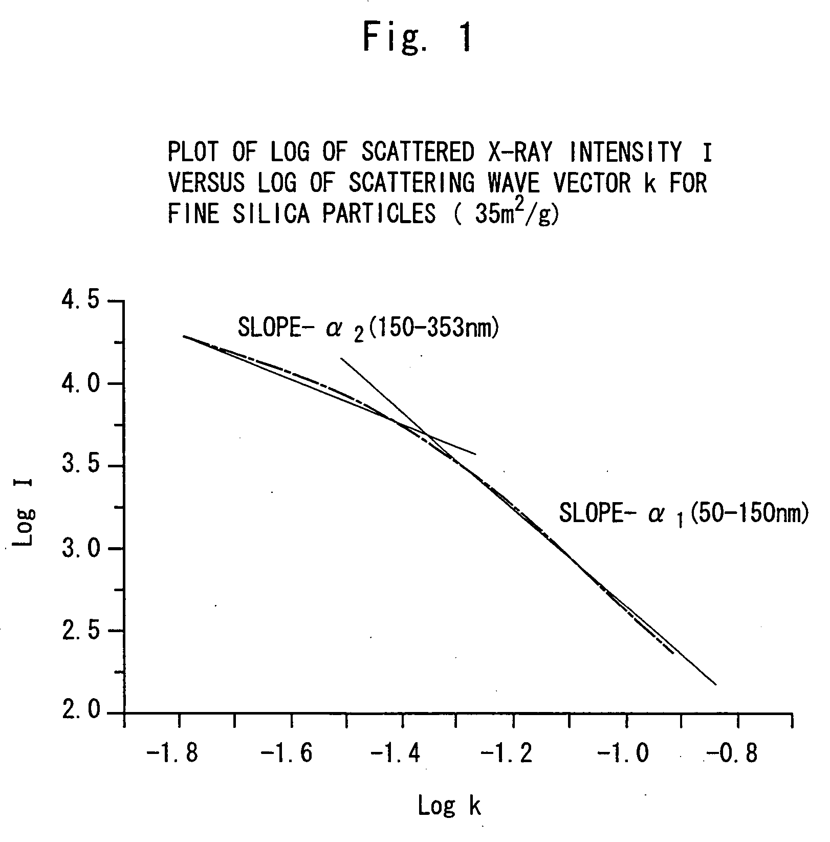
1. Measurement of Small-Angle X-Ray Scattering.
[0064] The sample fine silica particles were filled in a through hole (40 mm deep, 5 mm wide, 1 mm high) in a base plate, and both sides of the filled sample were held by 6 μm-thick polypropylene films. The measurement was taken using a biaxial small-angle X-ray scattering apparatus (M18XHF22) equipped with the Kratzky-U-slit manufactured by Mac Science Co. under the following conditions.
[0065] X-ray: Cu—Kα ray
[0066] Tube voltage: 40 kV
[0067] Tube current: 300 mA
[0068] Slit width: 10 μm
[0069] Detector scanning angle: 0.025 deg to 0.900 deg
2. Measurement of Average Particle Size.
[0070] A median particle size (D50) based on volume was measured using a laser scattering particle size distribution analy...
examples 1 to 4
[0099] Fine silica particles shown in Table 2 were produced by burning and oxidizing an octamethylcyclotetrasiloxane in an oxygen-hydrogen flame under the conditions described in Table 1.
[0100] Table 1 also shows average particle sizes, BET specific surface areas, fractal structure parameters α1 and α2 of the obtained silica particles and viscosity of the resin compounds comprising the obtained silica as well as strength of the cured resin compounds. The viscosity of Examples was not enhanced compared with that of Comparative Examples. Table 3 shows the concentrations of impurities in the silica.
examples 5 to 8
[0105] Fine silica particles were produced by combustion and oxidation of the octamethylcyclotetrasiloxane in the oxygen-hydrogen flame under the conditions described in Table 4.
[0106] Table 4 also shows average particle sizes, BET specific surface areas, and fractal structure parameters α1 and α2 of the obtained fine silica particles, as well as evaluated properties (free-flow property, image characteristics, cleaning property) as a toner additive for electrophotography. Table 5 shows the concentrations of impurities.
PUM
| Property | Measurement | Unit |
|---|---|---|
| Fraction | aaaaa | aaaaa |
| Length | aaaaa | aaaaa |
| Particle size | aaaaa | aaaaa |
Abstract
Description
Claims
Application Information