Low temperature, atmospheric pressure plasma generation and applications

a plasma and atmospheric pressure technology, applied in the field of plasma generation methods and apparatuses, can solve the problems of contaminating the material being treated, electrodes can be sputtered away, arcs are not easily scaled up to treat large areas, etc., and achieve the effect of reducing power inputs and efficient coupling of electrical power into electrodes

Inactive Publication Date: 2006-07-20
SURFX TECH
View PDF16 Cites 112 Cited by
  • Summary
  • Abstract
  • Description
  • Claims
  • Application Information

AI Technical Summary

Benefits of technology

[0017] One exemplary embodiment of the present invention comprises a device for generating the plasma at atmospheric pressure and temperatures below 400° C. This apparatus includes a non-conducting housing with a gas inlet and outlet, electrodes that are placed on the outer walls of the housing, a power supply operating at frequencies between approximately 1.0 and 500.0 MHz, and particularly at 13.56 MHz, and a matching network for efficiently coupling the electrical power into the electrodes. A particularly well-suited matching network for this embodiment is one that makes it possible to strike and maintain the plasma at substantially lower power inputs than in the prior art.

Problems solved by technology

Arcs are not easily scaled up to treat large areas.
Most importantly, the electrodes can be sputtered away, contaminating the material being treated.
In addition, plasma torches require large amounts of power to operate, adding to the complexity of the equipment, and posing some risk of electrical shock.
The disadvantage of this source is that the plasma directly contacts the electrodes and may sputter off material, thereby contaminating the substrate being processed.
As discussed above, this can result in sputtering of the electrodes and contamination of the wafer placed below the source.
Therefore, the design of this system is expensive and not versatile.
This design has several disadvantages: contamination may result from electrode sputtering; the plasma must be operated with at least 95 percent helium at high flow rates; and processing rates are relatively low.
These micro arcs can be eliminated by feeding certain gases to the discharge and operating at low current densities, but this severely limits the operating range of the device.
One of the disadvantages of DBDs is that the reactive species densities are relatively low.
This limits the type of objects that can be processed to thin sheets of material, such as plastic film.
Processing three-dimensional objects is not readily achievable with this design.
The problem with this design is that the electrodes do not efficiently couple the electric power into the gas, so that the fraction of the gas dissociating into reactive species is most likely small and not well suited for surface treatment.
The dual electrode design adds greatly to the complexity of this system.
In addition, the metal electrode used to strike the plasma is inserted directly into the gas flow, thereby providing a potential source of contamination, as described earlier.

Method used


Image

  • Low temperature, atmospheric pressure plasma generation and applications
  • Low temperature, atmospheric pressure plasma generation and applications
  • Low temperature, atmospheric pressure plasma generation and applications

Examples


example 1

Etching Polyimide

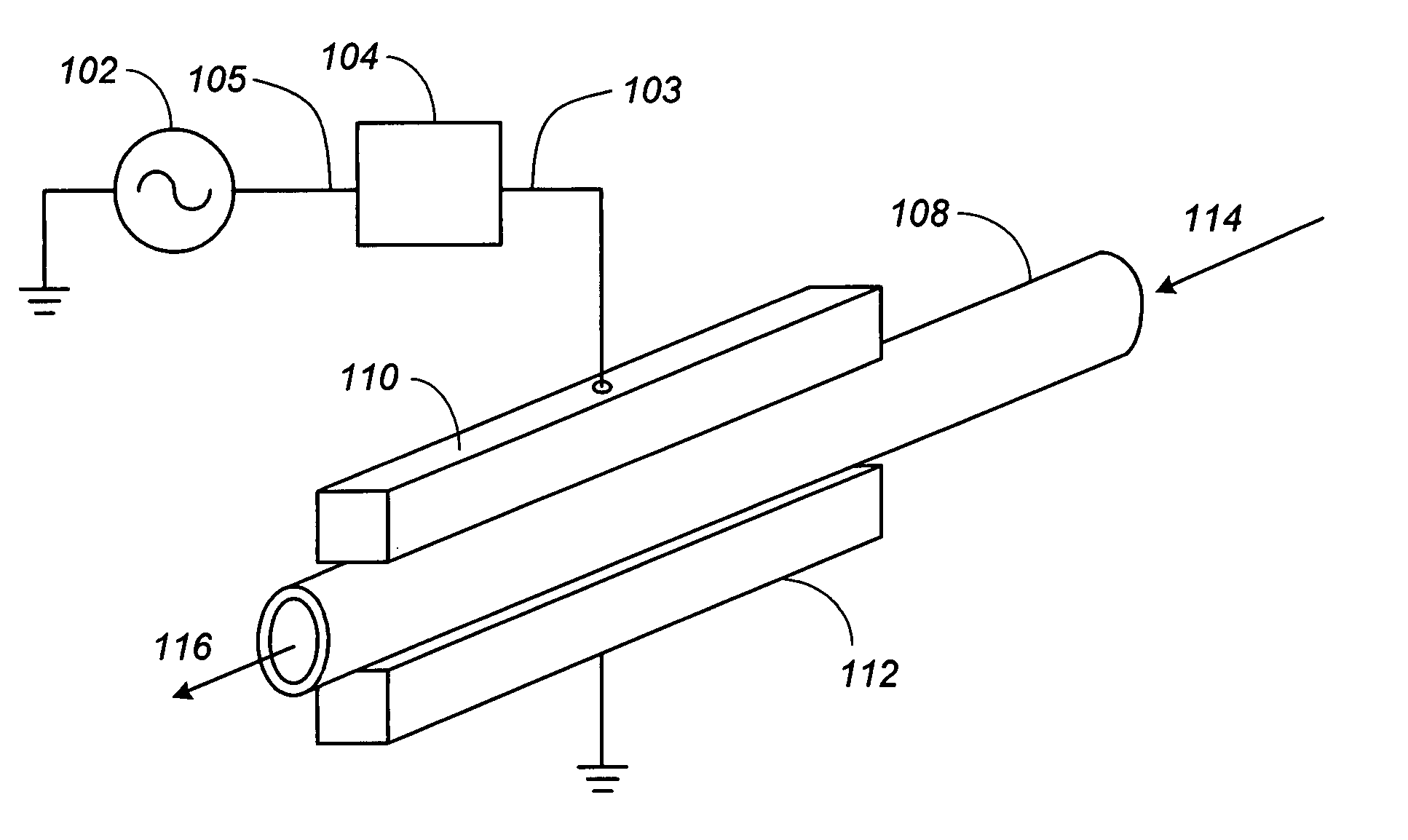
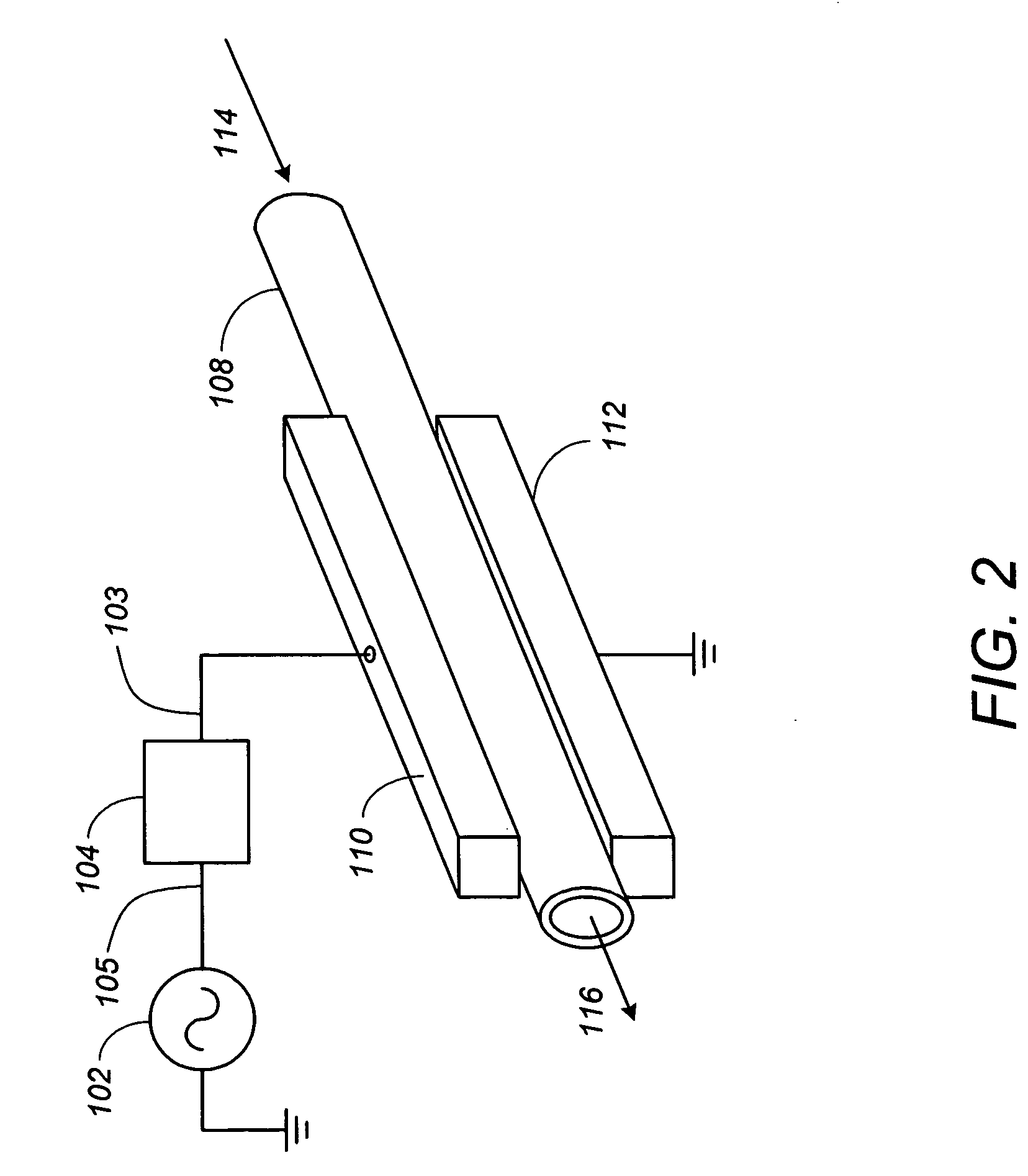
[0060] As an example of how one may practice the present invention, the apparatus shown in FIG. 2 was used to etch polyimide films. A mixture of argon and 5.5 volume percent oxygen was fed into a quartz tube, 3.0 mm in diameter, at a total flow rate of 4.6 L / min. Power was supplied to one of the electrodes at 13.56 MHz, while the other electrode was grounded. In the first experiment, the length of the discharge zone was 1.0 inch, and the power input was 90 W. The polyimide was placed 2.5 mm away from the end of the tube, yielding a gas temperature at this position of about 290° C. An etch rate through the polymer of 1.3 microns per second was obtained. In the second experiment, the length of the discharge zone was 2.5 inches, and the power input was 130 W. The sample was placed 1.0 cm away from the end of the tube, where the gas temperature was approximately 290° C. In this case, the etching rate of the polyimide film was 4.2 microns per second. These rates may be ...

example 2

Etching Silicon

[0061] Silicon films were etched using the low temperature atmospheric pressure plasma depicted in FIG. 2. A quartz tube, 3 mm in diameter, was used in this experiment, and the length of the discharge zone was 2.5 inches. The plasma was fed with 5.0 L / min argon and varying amounts of carbon tetrafluoride (CF4) between 0.5 and 2.3 volume percent. Upon applying 160 W / cm3 to the gas volume between the electrodes, a discharge was struck that yielded an extremely bright green glow. A silicon wafer was placed 1 cm downstream of the outlet of the quartz housing, and the plasma beam was allowed to impinge on the wafer for several minutes. Afterwards, the depth of the hole etched into the wafer was measured with a Deptak profilometer. The results of this experiment are presented in FIG. 12. A silicon etch rate of about 2.0 microns per minute was achieved with 0.5 volume percent CF4, whereas between 1.0 and 2.0 volume percent CF4, the etch rate averaged 1.3 microns per minute....

example 3

Surface Activation

[0063] Another example of how one may practice the present invention is to modify the surface of plastic or other materials. For example, the discharge can be used to change the wettability of the surface. In this case, a hydrophobic material can be processed to become more hydrophilic or visa versa by treating it with oxygen or hydrogen plasmas. By making a plastic surface more hydrophilic, it can better accept paints or inks for printing, and glue for making strong adhesive bonds.

[0064] Plastic samples were treated with the apparatus shown in FIG. 2 under the following conditions: 5.0 L / min argon gas flow, 0.2 L / min oxygen gas flow, 200 W of power at 13.56 MHz, and a distance from the plasma outlet to the sample of about 1.0 cm. The plasma exposure time was 0.5 seconds. Before and after plasma treatment, the surface energy of each material was measured with Accu Dyne Test markers. It was found that the surface energies changed as follows: polypropylene increase...


PUM

PropertyMeasurementUnit
inner diameteraaaaaaaaaa
heightaaaaaaaaaa

Abstract

Devices and methods for generating a low temperature atmospheric pressure plasma are disclosed. A method of generating a low temperature atmospheric pressure plasma that comprises coupling a high-frequency power supply to a tuning network that is connected to one or more electrodes, placing one or more non-conducting housings between the electrodes, flowing gas through the one or more housings, and striking and maintaining the plasma with the application of said high-frequency power is described. A technique for the surface treatment of materials with said low temperature atmospheric pressure plasma, including surface activation, cleaning, sterilization, etching and deposition of thin films is also disclosed.

Description

CROSS-REFERENCE TO RELATED APPLICATIONS [0001] This application claims the benefit under 35 U.S.C. §119(e) of the following U.S. provisional patent applications, which are both incorporated by reference herein: [0002] U.S. Provisional Patent Application No. 60 / 645,546, filed Jan. 19, 2005, and entitled “METHOD AND APPARATUS FOR GENERATING A LOW TEMPERATURE, ATMOSPHERIC PRESSURE PLASMA AND USE THEREOF”, by Penelon et al.; and [0003] U.S. Provisional Patent Application No. 60 / 682,336, filed May 18, 2005, and entitled “LOW-TEMPERATURE, REACTIVE GAS SOURCE AND METHOD OF USE”, by Penelon et al.BACKGROUND OF THE INVENTION [0004] 1. Field of the Invention [0005] The invention is related to methods and apparatuses for generating plasmas. Particularly, the invention is related to methods and apparatuses for generating a low temperature, atmospheric pressure plasma, and its use for surface treatment and the deposition of thin films. [0006] 2. Description of the Related Art [0007] Plasmas are ...

Claims


Application Information

Patent Timeline
Patent Type & Authority Applications(United States)
IPC IPC(8): B01J19/08C23F1/00C23C16/00
CPCA61L2/14C23C16/402C23C16/507C23F4/00H05H1/24H05H1/246
Inventor PENELON, JOELMOTYCKA, SYLVAINBABAYAN, STEVEYANG, XIAWAN
Owner SURFX TECH
Why Eureka
Try Eureka