Method and apparatus for deployment of ocean bottom seismometers

a seismometer and ocean bottom technology, applied in underwater equipment, special-purpose vessels, instruments, etc., can solve the problems of simple complicated deployment and retrieval of seismic receiver units, and increased the likelihood of cable breakage or equipment failur

Active Publication Date: 2006-07-20
MAGSEIS FF LLC
View PDF69 Cites 168 Cited by
  • Summary
  • Abstract
  • Description
  • Claims
  • Application Information

AI Technical Summary

Benefits of technology

[0022] The present invention provides a system for deep water deployment and retrieval of OBS units from a surface vessel or platform. The system utilizes at least one remotely operated vehicle (“ROV”) or similar device to which is attached a carrier apparatus in which is seated multiple, independently deployable OBS units. In most of the preferred embodiments, the carrier apparatus is attached directly to the ROV. As such, the ROV itself is used to carry the OBS units down to the seabed from the surface vessel. Once adjacent the seabed, the ROV can efficiently move between desired “node” locations in order to plant an OBS for operation. Preferably, the individual units can either be automatically ejected from the carrier apparatus or alternatively extracted and placed with the assistance of a robotic arm or similar manipulation device carried on the ROV / carrier system.
[0023] In one preferred embodiment, the carrier apparatus consists of a moving or rotating carousel on which the OBS units are carried. The carousel rotates in order to position an OBS unit for deployment from the carrier. Such deployment may be automatic or require external assistance, such as a robotic arm located on the carrier or ROV. A carousel such as this is desirable because it not only simplifies deployment from the carrier, but it also permits the carrier “load”, i.e., the OBS units, to be shifted in order to control weight balance and buoyancy of the ROV / carrier system.
[0030] In each case, by utilizing an ROV or similar remote deployment mechanism, OBS units can be placed accurately on the seabed in the desired position. Likewise, proper orientation can be ensured, as can a high degree of coupling. In the preferred embodiment, each OBS unit is wireless and self-contained so that no communication or control is required between the ROV and the OBS units. In this embodiment, operation of the OBS units is initiated prior to deployment from the deck of the deployment vessel, or alternatively, prior to handling by the ROV at the seabed. In another embodiment, the OBS unit and the ROV are each equipped with a wireless communication device, such as an acoustic or electromagnetic modem, so that the ROV can be utilized to communicate with the OBS unit when the unit and the ROV are in “wireless” range of one another. This permits communication with the OBS unit for purposes such as activation, operation and quality control.

Problems solved by technology

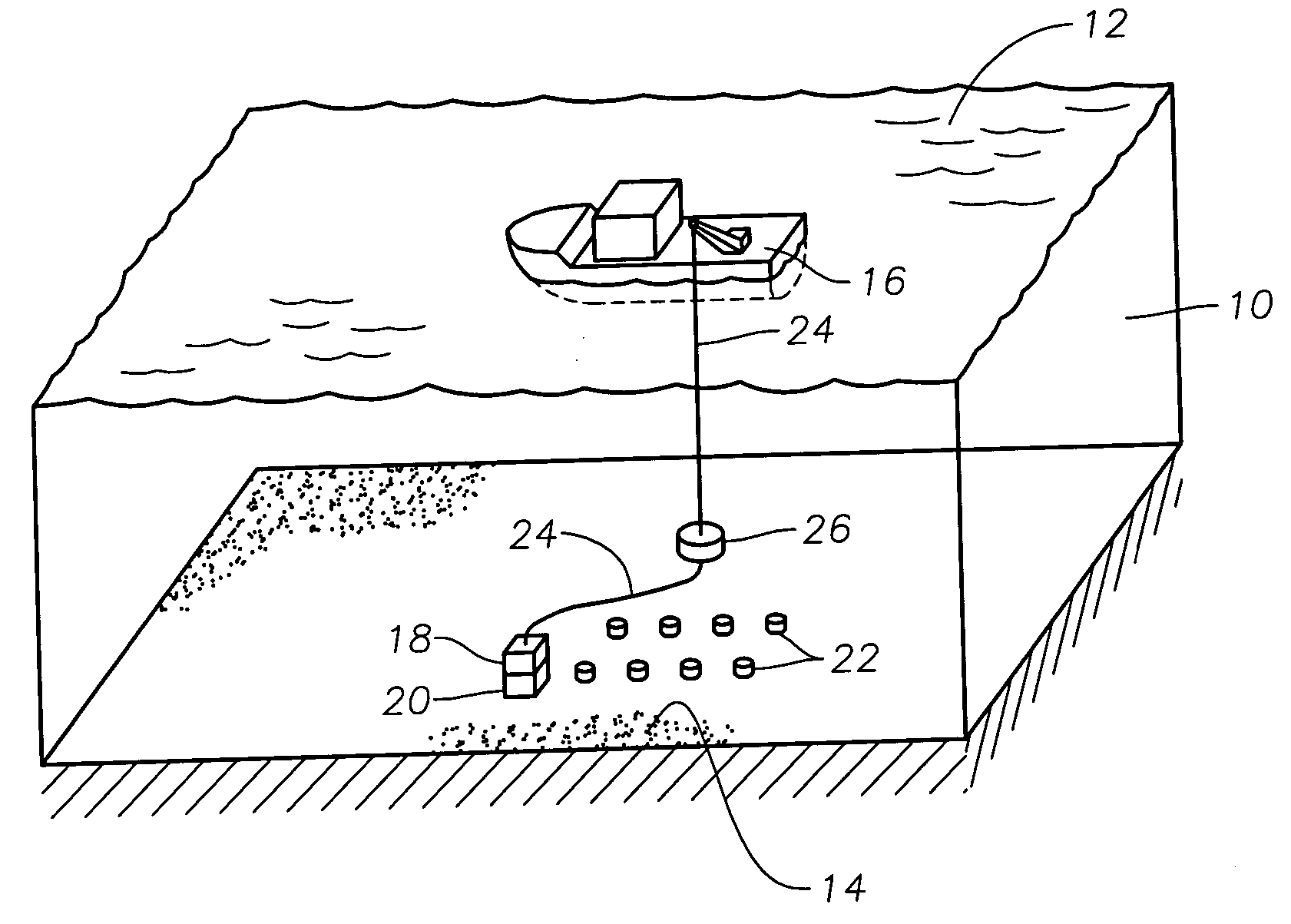
While the fundamental process for detection and recording of seismic reflections is the same on land and in marine environments, marine environments present unique problems due to the body of water overlaying the earth's surface.
In marine environments, even simple deployment and retrieval of seismic receiver units is complicated since operations must be conducted off the deck of a seismic exploration vessel, where external elements such as wave action, weather and limited space can greatly effect the operation.
Because the recording vessel is in constant physical contact with the cable, the effort required to maintain the vessel's position to counter wave action and ocean currents can generate great tension within the cable, increasing the likelihood of a broken cable or failed equipment, as well as the introduction of signal interference into the cable.
Any misorientation of the OBS system on the seabed can result in clock inaccuracies.
Likewise, while mechanical gimbals may be used to correct for tilt, pitch in many mechanical gimbal devices is limited 30°.
Of course, it is well known that mechanical gimballing of a geophone is expensive and requires more space than a non-gimballed geophone, and as such, it is desirable to deploy an OBS system so as to render gimballing unnecessary.
One problem that is common in all types of seismic systems physically deployed on the seabed is the degree of coupling between the system and the seabed.
As such, horizontal motion other than that due to the sediment, such as for example, ocean bottom currents, can cause erroneous signals.
Likewise, because of its elongated structure, OBC systems tend to have satisfactory coupling only along the major axis of the cable when attempting to record shear wave data.
Not only is the unit likely to be of little value in the seismic survey because of its misplacement, locating and retrieving the OBS unit becomes much more difficult.
Such processing typically necessitates additional equipment on-board the unit itself to determine x, y and z orientation, as well as additional computational power and time during processing of the raw data.
Likewise, the degree of coupling between a seismic collection unit and the sea floor, whether in shallow water or deep water, is often difficult to determine at the time a unit is positioned.
In many cases, the top layer of silt at a particular location on the sea floor may be somewhat unstable or mushy, such that seismic energy transmission therethrough to the seismic unit is attenuated or distorted in some way.
Because the push to conduct seismic operations in deep water is relatively recent, few attempts have been made to address the above-mentioned problems associated with deep water deployment of OBS units.
Those skilled in the art will understand that such a system will likely encounter operational problems in light of the rigors of deep water operations where extreme depths, surface conditions, multiple ocean currents and mushy or unstable sea bottom conditions can all significantly affect the deployment effort Most notably, the drag on the carrier, the ROV and their respective lines are all different, and as such, these different components of the deployment system will have disparate responses under water when subject to the various elements.
In the case of the carrier cage, there is no mechanism for remotely controlling the position of the cage in the water, the result being that the cage is highly likely to be pulled along in the direction of the prevailing ocean currents with very little control over the cage's movement.
Perhaps even more threatening to such a system under actual operating conditions is the likelihood that the lines will become tangled, interrupting a seismic shoot and threatening profitability.
Those skilled in the art understand that as the number of lines in the water at any given time increases, the more complicated the operation becomes and the more difficult it becomes to control movement of the lines and prevent tangling.
Even when the end of one line is controlled by an ROV, but the other is not, entanglement is likely.
Since a typical deployment boat may be only 40 feet wide and each line is deployed on opposite sides of the boat, there is a high probability that the carrier cage line will become entangled with the ROV tether.
An additional drawback to the above-described prior art system is that it utilizes only a single ROV for deployment and retrieval.
Any breakdown of the ROV can substantially delay the deployment / retrieval efforts since repairs would be necessary before continuing.

Method used


Image

  • Method and apparatus for deployment of ocean bottom seismometers
  • Method and apparatus for deployment of ocean bottom seismometers
  • Method and apparatus for deployment of ocean bottom seismometers

Examples


Embodiment Construction

[0049] In the detailed description of the invention, like numerals are employed to designate like parts throughout. Various items of equipment, such as fasteners, fittings, etc., may be omitted to simplify the description. However, those skilled in the art will realize that such conventional equipment can be employed as desired.

[0050] With reference to FIG. 1, there is shown a body of water 10 having a surface 12 and a seabed 14. A vessel or operations platform 16 is positioned on the surface 12 of the water 10. A remotely operated vehicle (“ROV”) or similar device 18 is in communication with vessel 16. A carrier 20 is attached to ROV 18. Carrier 20 is disposed for receipt of a plurality of ocean bottom seismic receiver units 22. ROV 18 is capable of moving between surface 12 and seabed 14 in order to ferry ocean bottom seismic receiver units 22 therebetween. ROV 18 may also be utilized to remove units 22 from carrier 20 and place units 22 on seabed 14. Likewise, ROV 18 may be util...


PUM


Abstract

A method and apparatus for deployment and retrieval of ocean bottom seismic receivers. In one embodiment, the apparatus comprises a carrier containing a plurality of receivers attached to a remotely operated vehicle (ROV). The carrier comprises a frame in which is mounted a structure for seating and releasing said receivers. The structure may comprise a movable carousel or a movable conveyor or fixed parallel rails or a barrel. In the case of the barrel, the receivers are axially stacked therein. The structure is disposed to deliver said receivers to a discharge port on said frame, where the receivers are removable from said carrier. The apparatus includes a discharge mechanism for removing said receivers from said carrier. In another embodiment, the method comprises the steps of loading a carrier with a plurality of receivers, attaching said carrier to an ROV, utilizing said ROV to transport the carrier from a surface vessel to a position adjacent the seabed and thereafter utilizing said ROV to remove receivers from said carrier and place the receivers on the seabed. In yet another embodiment, an ROV adjacent the seabed engages a deployment line extending from the vessel. The deployment line is used to guide receivers attached thereto down to the ROV for “on-time” delivery and placement on the seabed.

Description

BACKGROUND OF THE INVENTION [0001] The present invention relates to the field of seismic exploration. More particularly, the invention relates to a method and apparatus for seismic exploration, and most particularly to deployment and retrieval of ocean bottom seismometer systems in deep marine environments. [0002] Seismic exploration generally utilizes a seismic energy source to generate an acoustic signal that propagates into the earth and is partially reflected by subsurface seismic reflectors (i.e., interfaces between subsurface lithologic or fluid layers characterized by different elastic properties). The reflected signals (known as “seismic reflections”) are detected and recorded by seismic receiver units positioned at or near the surface of the earth, thereby generating a seismic survey of the subsurface. The recorded signals, or seismic energy data, can then be processed to yield information relating to the lithologic subsurface formations, identifying such features, as, for ...

Claims


Application Information

Patent Timeline
Patent Type & Authority Applications(United States)
IPC IPC(8): B63C11/10
CPCB63C11/00B63G8/00B63G2008/004G01V1/3852B63G8/001B63B22/00B63B22/18B63B2211/02B63G2008/005B63G2008/007G01V1/3861
Inventor THOMPSON, JAMES N.RAY, CLIFFORD H.FISSELER, GLENN D.FYFFE, ROGER L.
Owner MAGSEIS FF LLC
Why Eureka
Try Eureka