Method of joining ceramics: reaction diffusion-bonding

a technology of diffusion bonding and ceramics, applied in the field of joining compound materials, can solve the problems of reducing the thermal and chemical stability of the ceramic system, reducing and the industrial product is very rarely monolithic, so as to achieve superior thermal, mechanical, electrical and electronic, and electromagnetic characteristics. the effect of preserving the structural integrity of the material

Inactive Publication Date: 2006-07-27
CERAWEL
View PDF17 Cites 65 Cited by
  • Summary
  • Abstract
  • Description
  • Claims
  • Application Information

AI Technical Summary

Benefits of technology

[0022] Accordingly, individual pieces of ceramic materials can be directly bonded to form a large-sized one-body structure through the joining process according to an embodiment of the present invention. This reaction diffusion-bonded ceramics structure has suitable characteristics for application to practical fields because it possesses almost the same mechanical, optical, electrical and electronic, electromagnetic, thermal, chemical, and crystallographic characteristic as the individual pieces of the parent materials, and maintains the structural integrity of the materials. A method of reaction joining according to an embodiment of the present invention can be used to overcome the drawbacks and difficulties of the conventional methods of joining, and the ceramic parts joined according to embodiments of the present invent ion has various advantages such as superior thermal, mechanical, chemical, electrical and electronic, and electromagnetic characteristics compared to the parts prepared by a conventional method.

Problems solved by technology

However, industrial products are very rarely monolithic.
The problem of joining components is therefore a key issue in the design process.
However, metal brazing, glass frit bonding, and adhesive bonding principally reduce the thermal and chemical stability of the ceramic system.
These disadvantages originate from the presence of an additional material (glue or solder) with completely different properties from those of the ceramics.
Furthermore, mechanical fastening is frequently inadequate because ceramic parts are inherently brittle, and fusion welding by laser or an electron beam cannot be widely applied to the joining of ceramics because of incompatibilities due to excess localized stresses which cannot be accommodated by a stiff material and the possible thermal decomposition of the ceramics during the welding process.
The co-sintering process for joining ceramics is also successful only in some limited systems because of the difficulties in handling components to be joined, due to their weak mechanical strengths.
However, most ceramic materials do not readily deform and the diffusion process is rather slow except at extremely high temperatures, and thus rarely successful.
Currently no technology exists that, within reasonable economical limits, produces joints of satisfactory quality between ceramic parts and preserves the excellent properties of the ceramic material.
The lack of a well-developed joining technology for ceramics limits or prevents the use of ceramics in a range of applications.
The problems associated with joining ceramics for high temperature applications are particularly severe.
The major limitation of sapphire for use in window and ballistic protection applications is that it cannot be produced in a size large enough to meet some proposed system requirements.
Scaling current sapphire crystal growth processes to produce the desired window sizes is cost prohibitive and technically risky; and growing high quality, homogeneous crystals in much larger diameters may have intrinsic limitations.
However, this method does not provide sufficient direct bonding between the sapphires due to the formation of a MgAl2O4 spinel phase between the coated MgO and the sapphire at the joining interface during heat treatment.

Method used


Image

  • Method of joining ceramics: reaction diffusion-bonding
  • Method of joining ceramics: reaction diffusion-bonding
  • Method of joining ceramics: reaction diffusion-bonding

Examples


example 1

Sapphire Joining-1

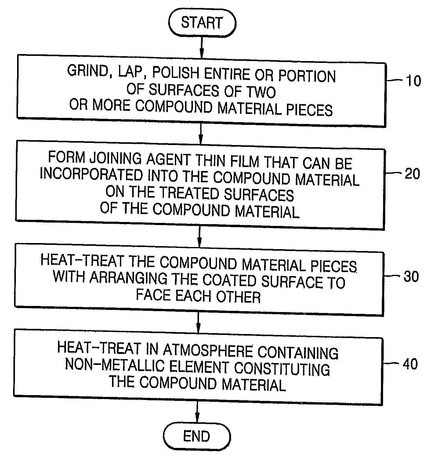
[0051] A white sapphire was cut to have a desired crystallographic orientation, size, and shape, and the cut surfaces were polished by sequentially using diamond abrasives from 6 μm to 1 μm. The sapphire was cut in a disc shape with a thickness of 5 mm. A pure Al (99.9%) layer having a thickness of 2-4 μm was then deposited on the polished sapphire surface using a vacuum evaporator.

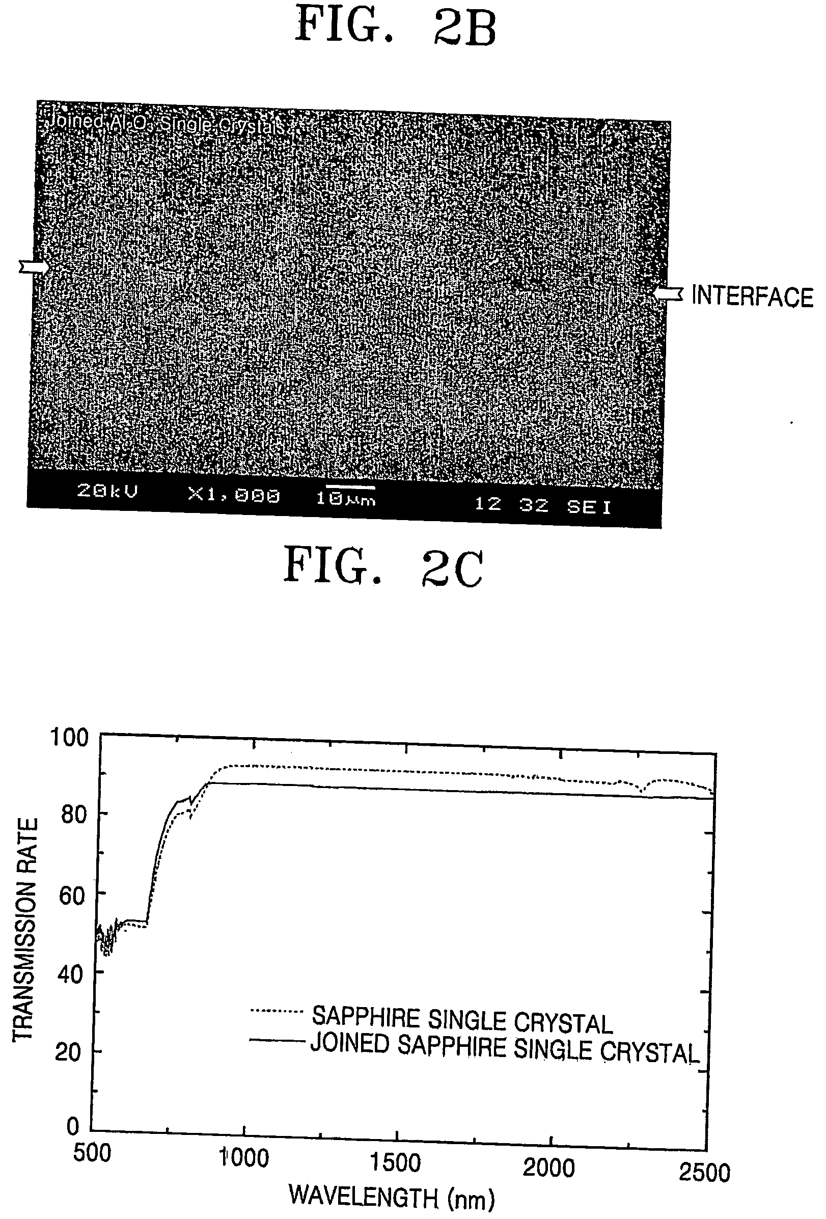
[0052] The deposited surfaces were then arranged to face each other, and heat-treated in a vacuum furnace or a hot press furnace. The heat treatment was performed at temperature in a range of 1,000-1,850° C. for 30 minutes to 2 hours under a pressure in a range of 0-30 MPa in the presence of argon gas. The temperature was increased at a rate of 10° C. per minute until 1,500° C., and at a rate of 5° C. per minute above this temperature. The heat treatment atmosphere can be performed in a vacuum state, or a gas containing hydrogen or oxygen can be used instead of argon. To increase optic...

example 2

Sapphire Joining-2

[0058] The second experiment was carried out under the same conditions as in Example 1, but an Al foil having a thickness of approximately 18 μm was inserted between the two polished surfaces instead of depositing an Al film. The pieces were heat-treated in a vacuum furnace or a hot press furnace. The heat treatment was performed at a temperature in a range of 600-1,850° C. under a pressure in a range of 0-30 MPa for 30 minute to 2 hours in the presence of argon gas. The remaining processes were the same in Example 1.

[0059]FIG. 3 is a photograph of the sapphire crystals joined in this second example using an Al foil. Referring to FIG. 3, the joined sapphire crystals have a strong joint strength and uniform characteristics.

example 3

Joining Al2O3 Ceramics

[0060] Poly-crystalline alumina pieces were prepared by sintering alumina (Al2O3) powder (AKP-50, Sumitomo, Japan) at 1,400° C. in a hot press furnace, and Al, as a joining agent, was deposited on the surfaces to be joined.

[0061] The pieces were arranged so that the to-be-joined surfaces faced each other and were heat-treated under the same conditions as in Example 1. The heat treatment was carried out at a temperature in a range of 1,000-1,850° C. for 30 minutes to 2 hours under a pressure in a range of 0-30 MPa in the presence of argon gas. The remaining steps were the same as in Example 1. The heat treatment can be performed in a vacuum state, or in the presence of a gas containing hydrogen or oxygen instead of argon.

[0062]FIG. 4A is a photograph of Al2O3 ceramics joined in this example. FIG. 4B is a magnified SEM image of the interface region of the joined Al2O3 ceramics in FIG. 4A As seen in FIG. 4B, when Al was used as a joining agent, the joined Al2O3...


PUM

PropertyMeasurementUnit
pressureaaaaaaaaaa
thicknessaaaaaaaaaa
temperatureaaaaaaaaaa

Abstract

Provided is a method of joining compound materials such as ceramics. The method is a combination of diffusion bonding and reaction bonding, which is called reaction diffusion bonding (RDB). The method includes: grinding, lapping, or polishing entire or portions of surfaces to be joined of two or more pieces of a compound material; forming a thin film of a joining agent on one or more of the ground, lapped, or polished surfaces by one of inserting, spreading, depositing, plating, and coating, the joining agent being able to transform into the compound material by being incorporated into the compound material or by forming a solid solution with the compound material upon heat treating; and forming a directly bonded interface without a second phase by heat treating the pieces of the compound material with the to-be-joined surfaces on which the joining agent film is formed arranged to face each other, wherein the joining agent thin film is composed of a material selected from the group consisting of metals, metal organics, and metal compounds.

Description

TECHNICAL FIELD [0001] The present invention relates to a method of joining materials, and more particularly, to a method of joining compound materials such as ceramics. BACKGROUND ART [0002] Excellent properties of ceramics, such as high temperature resistance, extreme hardness, high chemical resistance and lower density than metals, are the reason for the application of technical ceramics in the vast fields of electronics, automotive industry, aerospace, chemical industry and so on. However, industrial products are very rarely monolithic. The problem of joining components is therefore a key issue in the design process. There are at least two reasons for joining ceramics: to assemble a complex structure from single components of the same material, or to join dissimilar materials so that the properties of various materials contribute to the design. [0003] Joining ceramics enables us to obtain morphologies that may not otherwise be practical or even feasible. One of the most importan...

Claims


Application Information

Patent Timeline
Patent Type & Authority Applications(United States)
IPC IPC(8): B32B37/00C04B37/00C03C27/08C04B35/645C30B33/06
CPCB32B2315/02C03C27/06C03C27/08C04B35/64C04B35/645C04B37/003C04B37/006C04B2235/6581C04B2235/6582C04B2235/663C04B2237/086C04B2237/12C04B2237/121C04B2237/16C04B2237/343C04B2237/36C04B2237/365C04B2237/368C04B2237/52C04B2237/708C30B33/06
Inventor HAN, JOO-HWAN
Owner CERAWEL
Why Eureka
Try Eureka