Compound semiconductor multilayer structure, hall device, and hall device manufacturing method

a multi-layer structure and compound semiconductor technology, applied in the direction of galvano-magnetic hall-effect devices, instruments, galvano-magnetic devices, etc., can solve the problems of large mismatching between crystal lattice spacings in substrates, degradation of crystallinity and mobility, etc., to achieve high mobility characteristics, ease the mismatch, and high resistance

Inactive Publication Date: 2005-02-24
ASAHI KASEI ELECTRONICS CO LTD
View PDF20 Cites 11 Cited by
  • Summary
  • Abstract
  • Description
  • Claims
  • Application Information

AI Technical Summary

Benefits of technology

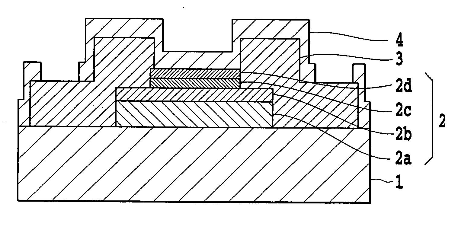
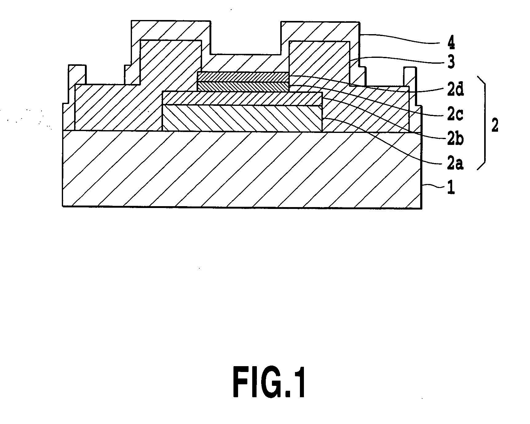
[0032] To implement both the high resistance and high mobility characteristics, it is necessary to ease the lattice mismatch between the substrate and the active layer by providing the active layer with such a multilayer structure that sandwiches buffer layers that have a lattice constant close to that of the active layer and has a high resistance. The multilayer structure allows the active layer to be reduced in thickness with maintaining the crystallinity.
[0033] Forming the magneto-sensitive pattern with such a multilayer structure film makes it possible to fabricate an ideal Hall device with such characteristics suitable for mobile equipment as high resistance, high sensitivity, and good temperature characteristics that have not been achieved up to now. Applying such a Hall device to the mobile equipment can facilitate the design of the equipment.
[0034] The inventors of the present invention disclose that the Vu+rVu variations increase because very weak currents flow through regions other than the active layer when the compound semiconductor layers with the large band gap, which are placed on and under the active layer, make contact with the metal electrode layer, and the amounts and paths of the currents differ slightly for terminals at four locations. Thus, they found that a device structure, in which all the surfaces (top surface and side surfaces) of the compound semiconductor layers are covered with the passivation, and the metal electrode layer makes contact with only the active layer without making contact with the compound semiconductor layers, is effective to fabricate a Hall device with small Vu+rVu variations.
[0035] In addition, the inventors of the present invention disclose that the conventional device structures cannot cover the semiconductor thin films with the passivation completely with good covering, but increases the characteristic variations because of the corrosion of the compound semiconductor layers including Sb susceptible to oxidation by moisture. Thus, they found that covering all the exposed surfaces of the compound semiconductor layer, that is, all the surfaces and side surfaces, directly with a passivation is effective to fabricate the device with small characteristic variations under the high temperature, high moisture conditions.
[0036] Furthermore, the inventors of the present invention disclose that the characteristic variations in the device increase in a high temperature (such as soldering) because of the instability of the interface conditions between a cap layer and the passivation, which is caused by damage such as oxidation on the cap layer, that is, on a GaAsSb layer surface, during an O2 ashing step or the like in the Hall device fabrication process. Thus, they found that it is effective for stabilizing the interface conditions between the cap layer and the passivation for fabricating the Hall device with high soldering heat resistance, to form the cap layer with InGaAs without containing Sb, and to inhibit the damage on the outermost surface of the semiconductor thin film by forming a passivation after forming the semiconductor thin films, followed by forming a magneto-sensitive pattern using the patterned passivation as a mask.

Problems solved by technology

The Hall devices up to now have a problem in that the thin active layers bring about degradation in the crystallinity and reduction in the mobility.
This is because since the active layers are formed immediately on the substrates, large mismatching occurs between crystal lattice spacings in the substrates and the active layers.

Method used


Image

  • Compound semiconductor multilayer structure, hall device, and hall device manufacturing method
  • Compound semiconductor multilayer structure, hall device, and hall device manufacturing method
  • Compound semiconductor multilayer structure, hall device, and hall device manufacturing method

Examples


example 1

[0139] On a GaAs substrate two inches in diameter, are successively formed by the molecular beam epitaxy (MBE) 600 nm Al0.55Ga0.45AsSb as the first compound semiconductor layer, 50 nm InAs as the active layer, 60 nm Al0.55Ga0.45AsSb as the second compound semiconductor layer, and 6 nm GaAsSb as the third compound semiconductor layer.

[0140] The Sb composition was calculated, according to Vegard's law, from accurate lattice constants obtained by a high resolution X-ray diffraction method based on a 4-crystal method using Ge (220) single crystals. The electric characteristics such as the electron mobility were evaluated from the measurement of the Hall effect by van der Pauw method.

[0141] Table 2 summarizes the thus obtained lattice constant difference, electron mobility and sheet resistance in accordance with the Sb compositions.

TABLE 2latticeconstantelectronsheetdifferencemobilityresistanceSbx(%)(cm2 / Vs)(Ω)0.8850.10191125280.9020.23197054770.9180.35206014280.9290.43213043990.9380...

example 2

[0152] On a GaAs substrate two inches in diameter, are successively formed by the molecular beam epitaxy (MBE) 600 nm Al0.55Ga0.45AsSb as the first compound semiconductor layer, 70 nm InAs as the active layer, 60 nm Al0.55Ga0.45AsSb as the second compound semiconductor layer, and 6 nm GaAsSb as the third compound semiconductor layer.

[0153] The Sb composition was calculated, according to Vegard's law, from accurate lattice constants obtained by the high resolution X-ray diffraction method based on the 4-crystal method using Ge (220) single crystals. The electric characteristics such as the electron mobility were evaluated from the measurement of the Hall effect by van der Pauw method.

[0154] Table 4 summarizes the thus obtained lattice constant difference, electron mobility and sheet resistance in accordance with the Sb compositions.

TABLE 4latticeconstantelectronsheetdifferencemobilityresistanceSbx(%)(cm2 / Vs)(Ω)0.8860.11165695350.9010.22173524910.9190.36188094340.9370.49201043900....

example 3

[0157] On a GaAs substrate two inches in diameter, are successively formed by the molecular beam epitaxy (MBE) 600 nm Al0.55Ga0.45AsSb as the first compound semiconductor layer, 35 nm InAs as the active layer, 60 nm Al0.55Ga0.45AsSb as the second compound semiconductor layer, and 6 nm GaAsSb as the third compound semiconductor layer.

[0158] The Sb composition was calculated, according to Vegard's law, from accurate lattice constants obtained by the high resolution X-ray diffraction method based on the 4-crystal method using Ge (220) single crystals. The electric characteristics such as the electron mobility were evaluated from the measurement of the Hall effect by van der Pauw method.

[0159] Table 5 summarizes the thus obtained lattice constant difference, electron mobility and sheet resistance in accordance with the Sb compositions.

TABLE 5latticeconstantelectronsheetdifferencemobilityresistanceSbx(%)(cm2 / Vs)(Ω)0.8920.15196057430.9040.24205186560.9180.35216735900.9340.47228455210....


PUM


Abstract

Hall device is provided by enabling stable provision of a quantum well compound semiconductor stacked structure. It has first and second compound semiconductor layers composed of Sb and at least two of five elements of Al, Ga, In, As and P, and an active layer composed of InxGa1-x,AsySb1-y (0.8≦x≦1.0, 0.8 <y≦1.0), which are stacked. Compared with the active layer, the first and second compound semiconductor layers each have a wider band gap, and a resistance value five times or more greater. The lattice constant differences between the active layer and the first and second compound semiconductor layers are each designed in a range of 0.0-1.2%, and the thickness of the active layer is designed in a range of 30-100 nm.

Description

TECHNICAL FIELD [0001] The present invention relates to a compound semiconductor stacked structure and a compound semiconductor Hall device using the structure, and their fabrication method. More specifically, the present invention relates to a stacked compound semiconductor Hall device with an active layer of InAs or the like, and aims to provide a highly sensitive, low power consumption magnetic sensor with excellent temperature characteristics using a stacked structure, which is a quantum well compound semiconductor stacked structure with high electron mobility and sheet resistance, and excellent temperature characteristics. [0002] In addition, the present invention relates to various devices for mobile equipment using the Hall device. BACKGROUND ART [0003] Generally, Hall devices are used for the rotation control and position detection of motors and for magnetic field detection, and find extensive application in such fields as brushless motor, noncontact open / close detection swi...

Claims


Application Information

Patent Timeline
Patent Type & Authority Applications(United States)
IPC IPC(8): G01R33/07H01L29/201H01L29/205H01L43/06H01L43/14
CPCG01R33/07H01L29/201H01L43/14H01L43/065H01L29/205H10N52/101H10N52/01H01L29/778H10N52/00
Inventor WATANABE, TAKAYUKISHIBATA, YOSHIHIKOUJIHARA, TSUYOSHIYOSHIDA, TAKASHIOYAMA, AKIHIKO
Owner ASAHI KASEI ELECTRONICS CO LTD
Why Eureka
Try Eureka