Spiral electrodeionization device with uniform operating characteristics

Inactive Publication Date: 2006-07-27
IONICS INC
View PDF12 Cites 27 Cited by
  • Summary
  • Abstract
  • Description
  • Claims
  • Application Information

AI Technical Summary

Benefits of technology

[0027] Flow may also be segregated on the concentrate side by oriented strands of a mesh spacer, or by bands of impermeable material placed on the spacer in an oriented pattern. In one preferred embodiment of this aspect of the invention, the dilute flow follows a path parallel to the axis of the cylindrical winding, and the concentrate flow is directed such that it remains in or flows parallel to a plane perpendicular to the axis. Thus, as bivalent metals such as calcium, followed by ions such as sulfate or carbonate, are successively removed from the axial dilute flow and enter the concentrate cells, each of the removed impurities remains in a band within the cell as it flows toward the cell outlet, and does not mix with the other removed species. The segregated flow effectively prevents scale from forming. In another or further embodiment of this aspect of the inve

Problems solved by technology

However, it is not entirely clear from the '528 patent or from the commercial product description why bead replacement is deemed necessary.
It is also possible, however, that the device described in the '528 patent was prone to scaling as a result of the minerals (such as calcium and silica) present in the local waters and the nature of fluid flows and electrical fields within the device, and that resin replacement was necessary in that particular context.
However, the rate or flow distribution and other factors governing all these effects are such that conditions of high concentration of specific ions, extreme pH, or flow stagnation may all arise in use, and certain combinations of these conditions may pose control problems, impair the efficiency or degree of treatment, or risk introducing irreversible membrane damage and/or localized occurrences of resin or membrane scaling within the device.
Some heterogeneous exchange membranes may swell by twenty percent, and wetted beds of exchange beads also increase their volume and may exert high pressure if unduly confined.
Such swelling may impair the flow impedance, or may affect the integrity of membranes or structural elements.
For spiral constructions, the dimensional instability of membrane and bead media, together with the local slippage introduced by winding at different radii, and the relatively large length of individual membranes, raise additional potential problem

Method used


Image

  • Spiral electrodeionization device with uniform operating characteristics
  • Spiral electrodeionization device with uniform operating characteristics
  • Spiral electrodeionization device with uniform operating characteristics

Examples


Embodiment Construction

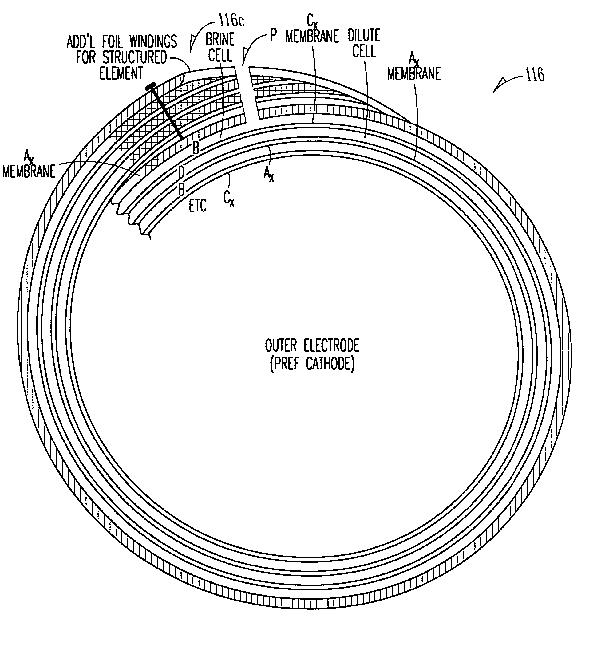
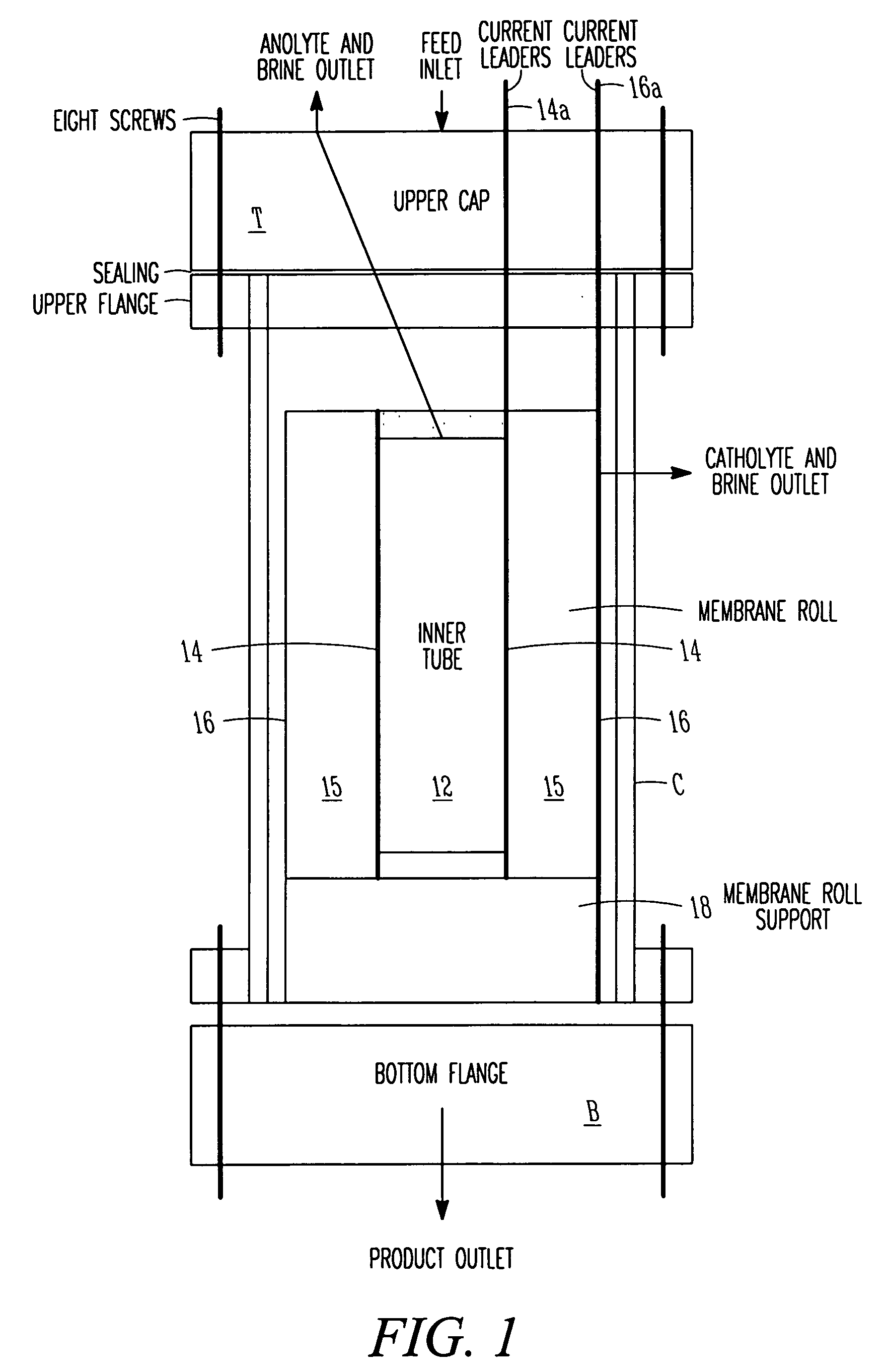
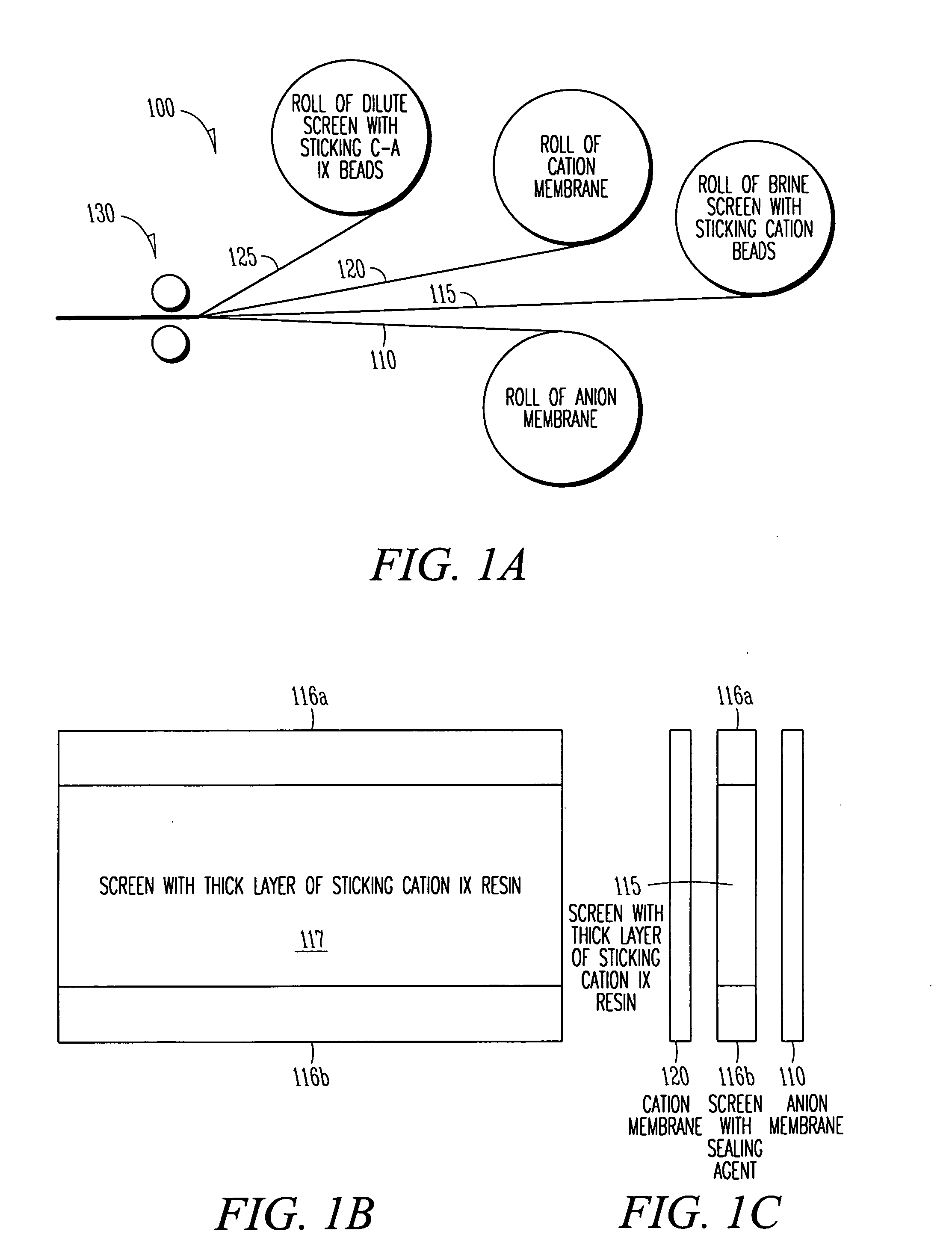
[0044]FIG. 1 is a schematic plan view of a first embodiment 10 of a cylindrical EDI apparatus in accordance with the present invention, showing general layout of components. The EDI apparatus 10 includes a housing illustratively comprised of a bottom flange plate B, a top flange plate T and a cylindrical body C that together define a generally cylindrical vessel or fluid-confining enclosing chamber. A membrane roll 15, of which several examples are described below, is wound around a central core 12 within the housing. Illustratively, a membrane roll support 18, the structure of which may take various forms, supports the membrane roll. An inner electrode 14 surrounds the central core 12, and is coupled to a first current leader 14a for connection to an external power source, and an outer electrode 16, coupled to a second current leader 16a, substantially surrounds the membrane roll 15. The membrane roll is wound in a spiral in the annular space between the two electrodes 14, 16. With...


PUM

PropertyMeasurementUnit
Flow rateaaaaaaaaaa
Diameteraaaaaaaaaa
Circumferenceaaaaaaaaaa

Abstract

EDI apparatus for demineralizing a liquid flow is assembled in a housing having a cylindrical shape, and includes two metal electrodes, and one or more leafs, each leaf comprising a pair of selectively ion-permeable membranes arranged parallel to each other and spaced apart by spacing elements that allow liquid to flow in the interstitial space between membranes, thus forming an arrangement of dilute and concentrate cells in a desired flow configuration. Spacing elements between membranes, as well as between leaves, can be formed of inert polymer material, ion exchange beads, ion exchange fibers, a combination of two or more these elements, or a porous media incorporating one or more of such elements as an intrinsic part. An inner or central electrode and an outer or perimeter electrode establish a generally uniform and radially-oriented electrical or ionic current between the inner and the outer electrodes, across the helical flow spaces defined by the membrane/spacer windings. One or both electrodes may include a pocket, and the adjacent flow cells lie parallel to the electrode and free of shadowing and field inhomogeneity around a full circumference of the electrode. Flow paths within the helical cells are defined by barrier seals, which may form a path-lengthening maze, while unfilled cell regions may disperse or collect flow within a cell and define pressure gradients promote directional flows. Impermeable barriers between membranes further prevent the feed and concentrate flows from mixing. In various embodiments, seals along or between portions of the flow path may define a multi-stage device, may define separate feed and/or concentrate flows for different stages, and/or may direct the feed and concentrate flows along preferred directions which may be co-current, counter-current or cross-current with respect to each other within the apparatus.

Description

REFERENCE TO RELATED APPLICATIONS [0001] This application claims the benefit of earlier-filed PCT International Application US2004 / 034909 filed Oct. 20, 2004, which claimed priority of U.S. Provisional Application Ser. No. 60 / 512,661 filed Oct. 20, 2003.BACKGROUND [0002] The present invention relates to methods and devices for demineralizing fluids, and relates to filtration or treatment cartridges or modules, having a generally cylindrical aspect and constructed with plies of spirally wound selectively-permeable membranes. It particularly relates to electrodialysis and electrodeionization devices, wherein the membranes possess ionic selectivity, and the device includes electrodes for inducing transport of species across the membranes by ionic conduction. [0003] In general, electrodialysis (ED) and so-called electrodeionization (EDI) devices operate by providing a structure that arranges flow channels such that a flow of a feed fluid that is to be treated is channeled between two io...

Claims


Application Information

Patent Timeline
IPC IPC(8): C25C7/02C25B9/19B01D61/46B01D61/48B01D61/52B01D63/10C02F1/461C02F1/469C25D17/00
CPCB01D61/46B01D61/48B01D61/52B01D63/10B01J47/08C02F1/4695C02F2001/46152C02F2201/003C02F2201/4611B01D61/463B01D63/101
Inventor GREBENYUK, VLADIMIRGREBENYUK, OLEGSIMS, KEITH J.CARSON, WILLIAM W.MACDONALD, RUSSELL J.ZHANG, LI
Owner IONICS INC
Why Eureka
Try Eureka