

Fuel cell
a fuel cell and cell technology, applied in the field of fuel cells, can solve the problems of increased diffusibility of hydrogen and increased permeation of hydrogen, and achieve the effect of reducing the pore volum
- Summary
- Abstract
- Description
- Claims
- Application Information
AI Technical Summary
Benefits of technology
Problems solved by technology
Method used
Image

Examples
example 1
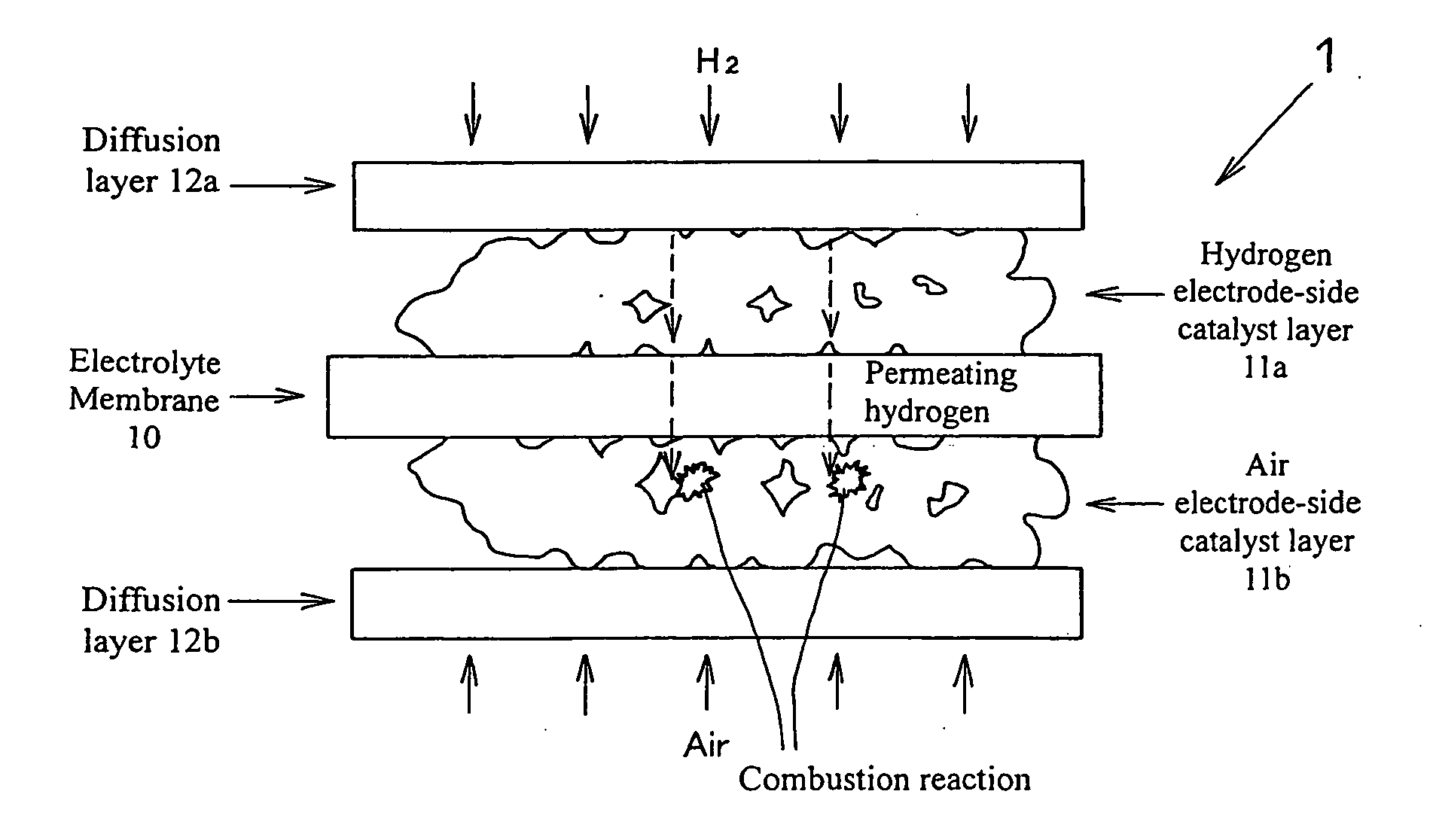
(1) Formation of Hydrogen Electrode-Side Catalyst Layer
[0022] To approximately 10 g of catalyst particles comprising carbon black (Vulcan XC-72, Cabot) having 15 wt % platinum particles supported thereon, 60 g of water and 45 g of ethanol are added in that order. The obtained solution is stirred well and mixed. Thereafter, 80 g of Nafion solution (DC-2020: 21% solution, DuPont) that serves as an electrolyte is added thereto, followed by stirring. The stirred solution is irradiated with sonic waves for approximately 1 minute using an ultrasonic homogenizer, followed by cooling for 5 minutes against subsequent heat generation. After this process has been repeated 10 times, the resulting dispersion solution that serves as a catalyst ink for a hydrogen electrode-side catalyst layer is obtained.
[0023] The dispersion solution is applied to a PTFE substrate by an applicator using a doctor blade technique. The amount of the solution applied is adjusted to result in a platinum weight of a...
example 2
(1) Formation of Hydrogen Electrode-Side Catalyst Layer
[0027] To approximately 10 g of catalyst particles comprising carbon black (Vulcan XC-72, Cabot) having 15 wt % platinum particles supported thereon, 60 g of water and 45 g of ethanol are added in that order. The obtained solution is stirred well and mixed. Thereafter, 40 g of Nafion solution (DC-2020: 21% solution, DuPont) is added thereto, followed by stirring. To the thus obtained solution, 4.3 g of titanium oxide (product name: MT-100AQ; average particle diameter: 0.24 μm, Tayca) that serves as an additive is added, followed by stirring. The stirred solution is irradiated with sonic waves for approximately 1 minute using an ultrasonic homogenizer, followed by cooling for 5 minutes against subsequent heat generation. After this process has been repeated 10 times, the resulting dispersion solution that serves as a catalyst ink for a hydrogen electrode-side catalyst layer is obtained.
[0028] The dispersion solution is applied...
example 3
(1) Formation of Hydrogen Electrode-Side Catalyst Layer
[0032] To approximately 10 g of catalyst particles comprising carbon black (Ketjen Black International Co., Ltd) having 45 wt % platinum particles supported thereon, 50 g of water and 50 g of ethanol are added in that order. The obtained solution is stirred well and mixed. Thereafter, 10 g of Nafion solution (DC-2020: 21% solution, DuPont) is added thereto, followed by stirring. The stirred solution is irradiated with sonic waves for approximately 1 minute using an ultrasonic homogenizer, followed by cooling for 5 minutes against subsequent heat generation. After this process has been repeated 10 times, the dispersion solution of the catalyst particles (catalyst ink) is obtained. The thus obtained dispersion solution is applied to an electrolyte membrane by spraying so as to form a hydrogen electrode-side catalyst layer.
(2) Formation of Air Electrode-Side Catalyst Layer
[0033] The above catalyst ink is applied to a PTFE subs...
PUM
| Property | Measurement | Unit |
|---|---|---|
| particle diameter | aaaaa | aaaaa |
| pore size | aaaaa | aaaaa |
| particle diameter | aaaaa | aaaaa |
Abstract
Description
Claims
Application Information