
Sensors for measuring analytes

a sensor and analyte technology, applied in the field of sensors, can solve the problems of inability to obtain accurate analyte concentration values inability to accurately measure oxygen,

Inactive Publication Date: 2006-08-03
DAKOTA TECH
View PDF46 Cites 47 Cited by
  • Summary
  • Abstract
  • Description
  • Claims
  • Application Information

AI Technical Summary

Benefits of technology

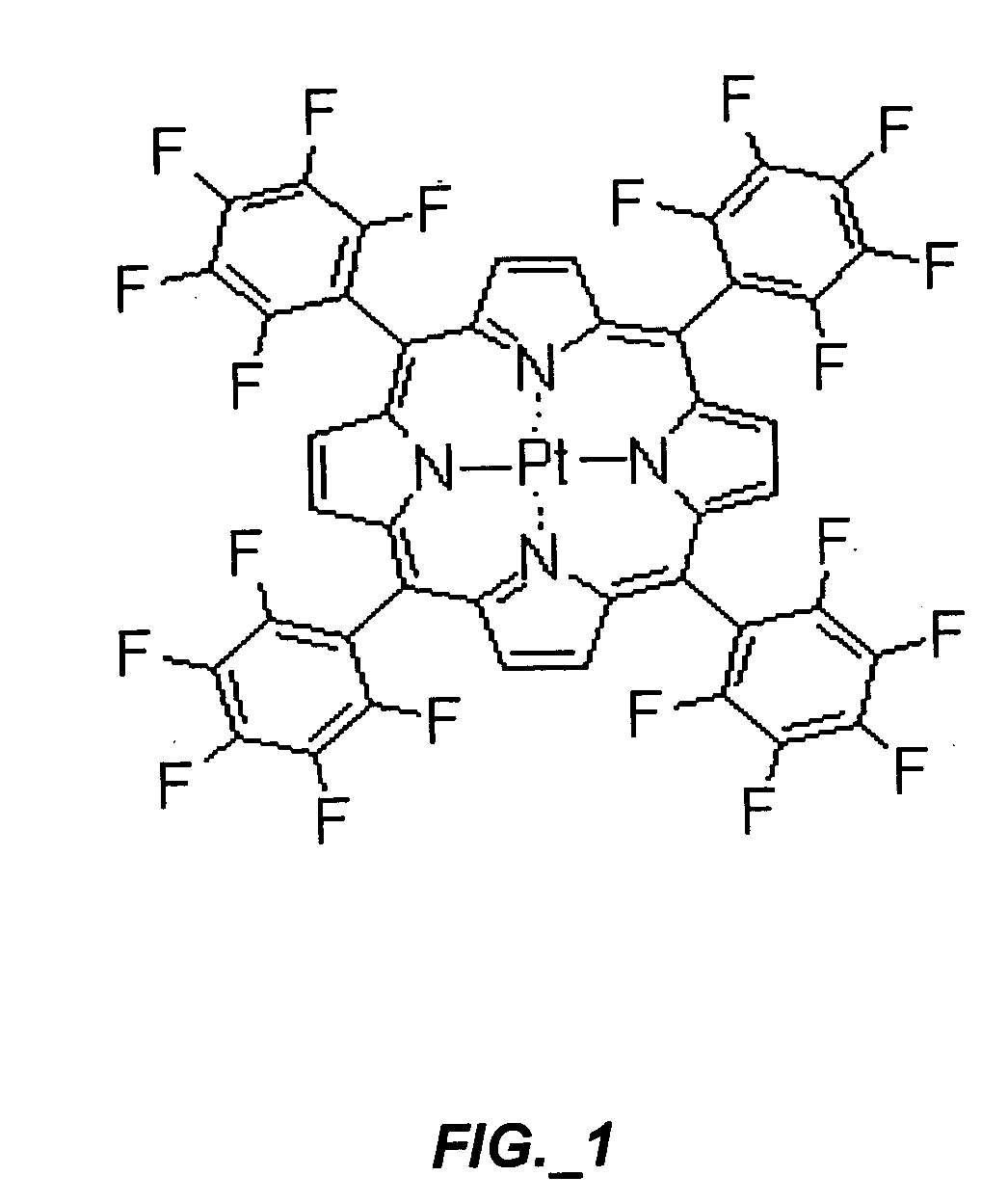
[0006] In some embodiments, the ligand in the metal-ligand complex is a macrocycle that binds and chelates the metal. Macrocycles, such as porphyrins that have been fluorinated to enhance solubility in the solvents used to introduce the metal-ligand into the polymer matrix, are found to be incorporated into the polymer matrix when exposed to the solvent-dye mixture. Once trapped within the polymer, the metal-ligand complexes are stably held within the polymer over long periods of time and show large Stokes shifts. In addition, the polymers may be processed to change the average pore size of the polymer matrix, thereby allowing formation of sensors that can exclude undesirable components from entering the polymer and interfering with measurement of the analyte of interest. These sensors are suited for measuring an analyte, such as oxygen, present in volatile organic solvents from different sources.
[0010] In other applications, the sensor in the form of film may be incorporated into vacuum packages, such as in containers for food and pharmaceuticals, to measure oxygen in the packages for purposes of quality control or to detect tampering. The sensor in the package is excited and the emitted light detected using an external unit containing the light source and the photodetector. The low cost of the sensor films described herein, their sensitivity, and durability are well suited for such large-scale commercial applications. The sensors may also be used in wastewater treatment plants, fermentation processes (e.g., wine and drug manufacture), and reactors used in polymer synthesis.

Problems solved by technology

If these components' concentrations vary with time, obtaining accurate analyte concentration values are difficult, if not impossible, to obtain.
In addition, variations in environmental factors, such as temperature and pressure can further create inaccuracies in analyte detection by their effects on the luminescent dye properties.
Accurate measurement of oxygen, however, is complicated by the significant variations in temperature and pressure experienced by the aircraft, and by differences in the composition of aviation fuel, which can vary depending on fuel source.
Electrolytic cells present explosion hazards, thus requiring complex systems to isolate the sensor from the fuel tank to minimize the hazard.
Currently available luminescent molecule based sensors are subject to physical or chemical degradation when exposed to volatile organic solvents (VOCs) present in aviation fuel, thus subjecting the dye molecule to interference by contaminants in the fuel composition and also degrading the performance of the sensor over time.

Method used


Image

  • Sensors for measuring analytes
  • Sensors for measuring analytes
  • Sensors for measuring analytes

Examples


example 1

[0060] Preparation of Oxygen Sensor

[0061] Swelling method. In one embodiment, the sensor construction procedure is as follows. A circular coupon with roughly ¼ inch diameter and 50 μm thickness is cut from a sheet of the amorphous fluorinated polymer. The dye is dissolved in octafluorotoluene. The amorphous fluorinated polymer coupon is then placed in contact with this dye-octafluorotoluene solution until the octafluorotoluene evaporates, or a sufficient amount of dye has been absorbed into the amorphous fluorinated polymer. Following drying, the sensor coupon is washed with acetone to remove residual dye from the surface. In another embodiment, the sensor construction includes treating a sheet of amorphous fluorinated polymer with the dye-octafluorotoluene solution, followed by cutting coupons out of the sheet.

[0062] Homogeneous solution method. In this method, the sensor is prepared from Pt(TFPP) dissolved in a suitable solvent together with Teflon AF 2400. Dissolving a small am...

example 2

[0065] Probe Design

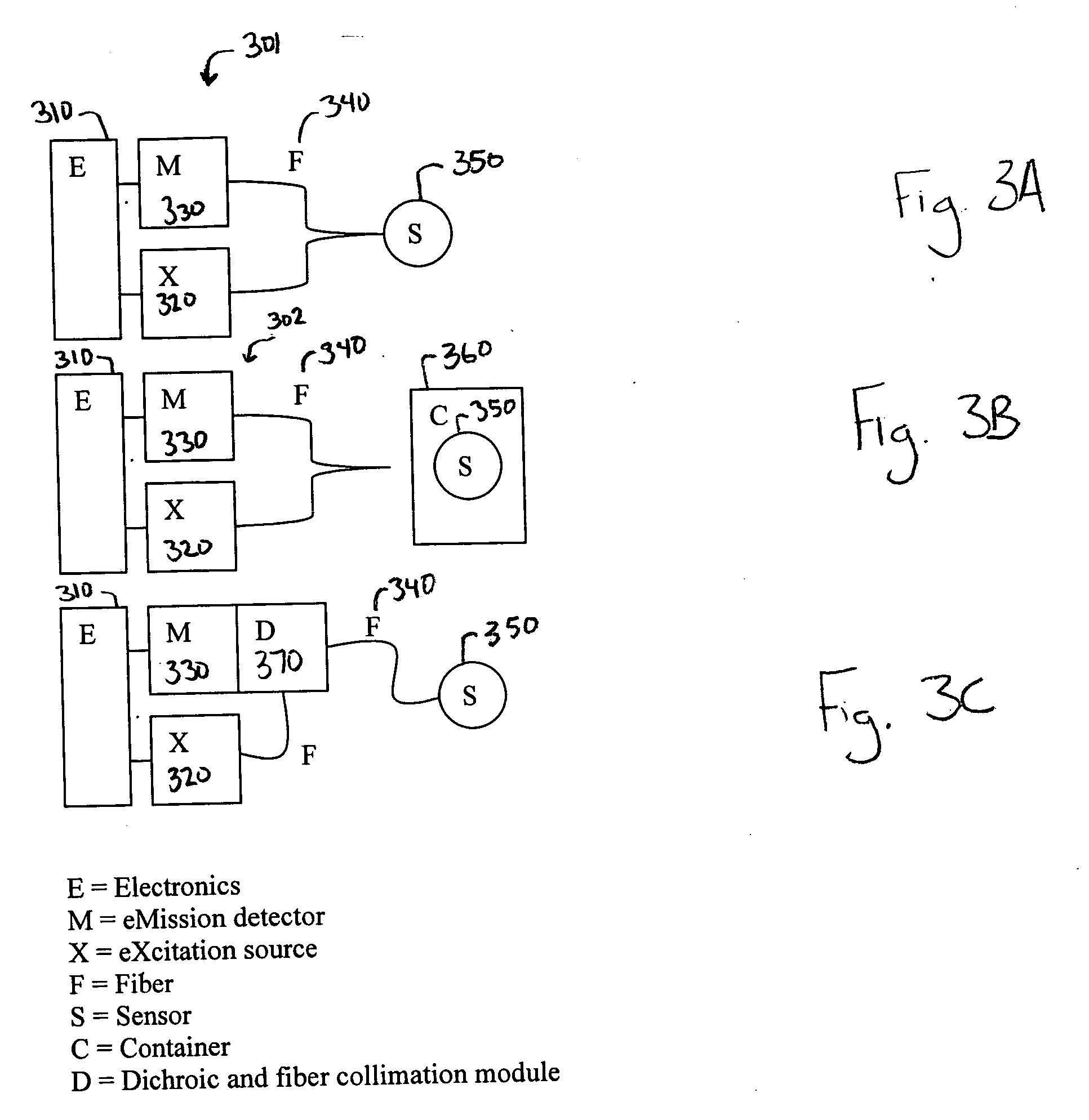
[0066] Generally, the sensor probe is designed to allow easy testing and interchangeability of sensor films. The probe may be a 2:1 design with two small-diameter fibers (one each for luminescence excitation and collection) coupled to a single large-diameter fiber. The ultimate diameters will be determined experimentally. This 2:1 design will serve two purposes. First, it will make it easy to swap out the large diameter fiber for testing and replacement and will ensure sufficient optical coupling of excitation light to the sensing film and emitted light back to the detector. In some embodiments, as further described below, the excitation light source is light from multiple LEDs in which a fiber optic line from each LED source is combined onto the larger diameter fiber.

[0067] The sensing film may be applied to the distal end of the large-diameter fiber. For probes that will not be exposed to liquid fuels or high concentration fuel vapors for prolonged periods, th...

example 3

[0068] Sensor System and Testing

[0069] Instrumentation. For a system using the analyte sensor described herein, the system used to record the sensor element's luminescence response includes LED sources, fiber optics, a wavelength selective emission filter, a photodetector, and an electronics package. The electronics consist of a Digital Signal Processor (DSP) running at 40 MHz clock speed and interfaced to a Complex Programmable Logic Device (CPLD) over the DSP's 16-bit databus. The CPLD has two 16-bit counters connected to high-speed comparators. The comparators monitor the photodetector to detect single photon events.

[0070] The light source is an array of eight 370 nm LEDs, operating in parallel, as further described below. The LEDs are driven by CMOS transistor pairs wired in an inverting configuration, with the LED in parallel with the P transistor. This configuration sharpens the falling edge of the LED excitation. LED pulsing is controlled by the DSP.

[0071] Owing to the rel...


PUM


Abstract

A sensor and system using the sensor for detecting an analyte, where the sensor includes an amorphous fluorinated polymer and a luminescent metal-ligand complex is provided. Sensor systems for monitoring oxygen in environments containing volatile organic solvents are also provided.

Description

TECHNICAL FIELD [0001] This invention relates to sensors, and more particularly to oxygen sensors and methods for their use. INTRODUCTION [0002] Many sensors used for detecting an analyte of interest are based on a luminescent molecule or dye, typically embedded in a polymer matrix permeable to the analyte, that changes its luminescence properties upon interaction with the analyte. However, in many applications there are components within the samples being monitored that are soluble in the sensor membrane matrix, which change the luminescent molecules' response to the analyte. For instance, competitive quenching may occur when components other than the analyte diffuse into the polymer matrix and change the luminescent molecules' emission properties. If these components' concentrations vary with time, obtaining accurate analyte concentration values are difficult, if not impossible, to obtain. In addition, variations in environmental factors, such as temperature and pressure can furth...

Claims


Application Information

Patent Timeline
IPC IPC(8): G01N21/00
CPCB64D37/32G01N21/643G01N21/7703G01N2021/6432G01N2021/6434G01N2021/6484
Inventor MARTIN, TRAVIS L.ENGEBRETSON, DANIEL S.
Owner DAKOTA TECH
Learn More