Method of magnetic resonance imaging

a magnetic resonance imaging and magnetic resonance technology, applied in the field of magnetic resonance imaging (mri), can solve the problems of inability to provide the desired contrast, inability to inability to achieve the desired contrast, etc., and achieve the effect of facilitating the visualisation of an invasive devi

Inactive Publication Date: 2006-08-03
GE HEALTHCARE AS
View PDF10 Cites 48 Cited by
  • Summary
  • Abstract
  • Description
  • Claims
  • Application Information

AI Technical Summary

Benefits of technology

[0009] Thus viewed from a first aspect, the invention provides a method of facilitating the visualisation of an invasive device in a human or non-human animal body by employing a contrast medium comprising a hyper...

Problems solved by technology

Related methods known from the prior art have drawbacks in that they expose the body under examination to high amounts of radiation, that distortions and artefact...

Method used


Image

  • Method of magnetic resonance imaging
  • Method of magnetic resonance imaging
  • Method of magnetic resonance imaging

Examples


example 1

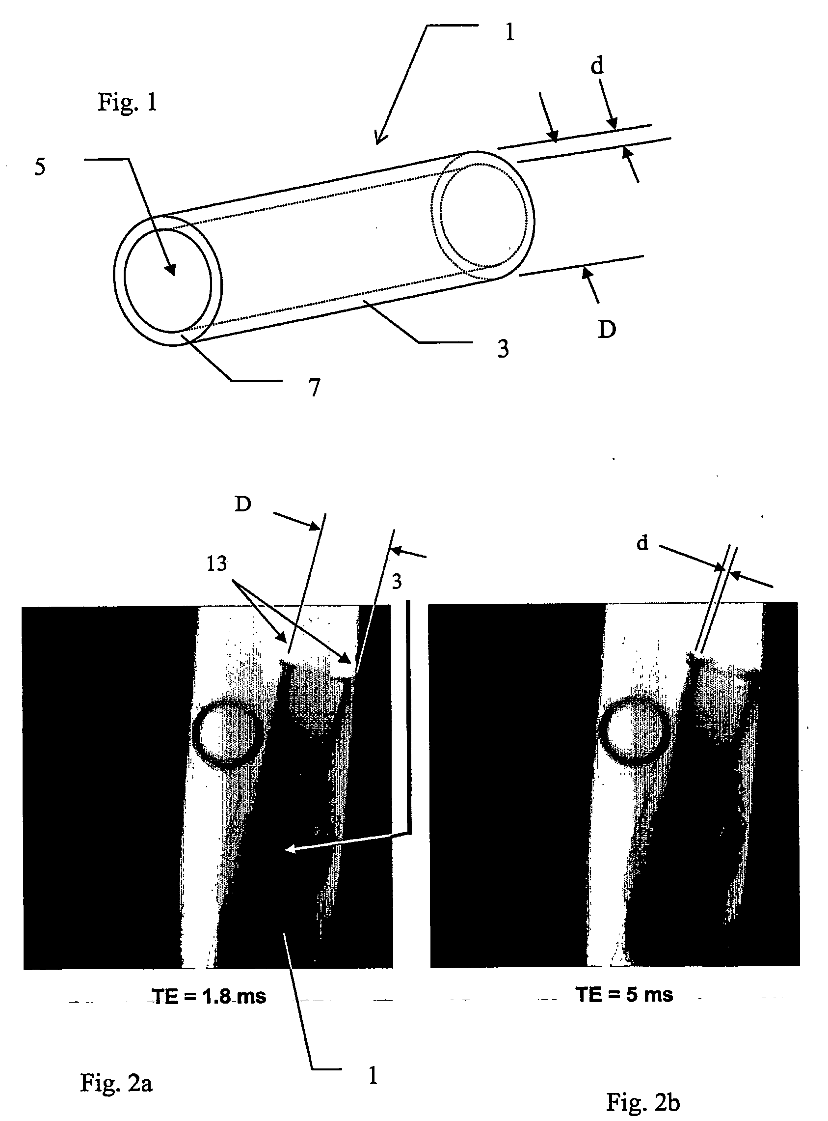
[0051] An aqueous solution of hyperpolaxised dimethylsuccinate (1-13C) was circulated in a closed loop moulded in a guide wire of glass-fibre reinforced plastic. The T1 of this compound under these circumstances is 70 s. The guide wire was inserted in the stomach of a rat and was imaged at the 13C frequency at 4 images per second. The images were colour coded and overlaid with a proton image of the rat. The guide wire is clearly visible in the rat as can be seen from the image in FIG. 5.

example 2

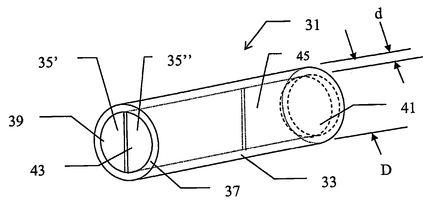
[0052]FIG. 2 shows the results of an experiment carried out using an invasive device (1) with a body (3) made from carbon fibre with a diameter D of 10 mm and a wall (7) thickness d of 1 mm. The electrical conductivity of the carbon fibre was ˜1·105 S / m (c.f. copper: 5.9·107 S / m). Device (1) was placed in a syringe containing water and imaged inside a 2.4 T magnet. Gradient echo images were acquired with echo time 1.8 ms as shown in FIGS. 2a and 5 ms as shown in FIG. 2b. Similar results were obtained with both echo times. Minor susceptibility artefacts (13) can be seen near the second open end of the invasive device. No signal is obtained from the lumen (3) of the of the device (except near to the second open end where radio frequency radiation has entered the lumen (3) from said second open end) showing that the wall of the invasive device is opaque to radio frequency radiation.

example 3

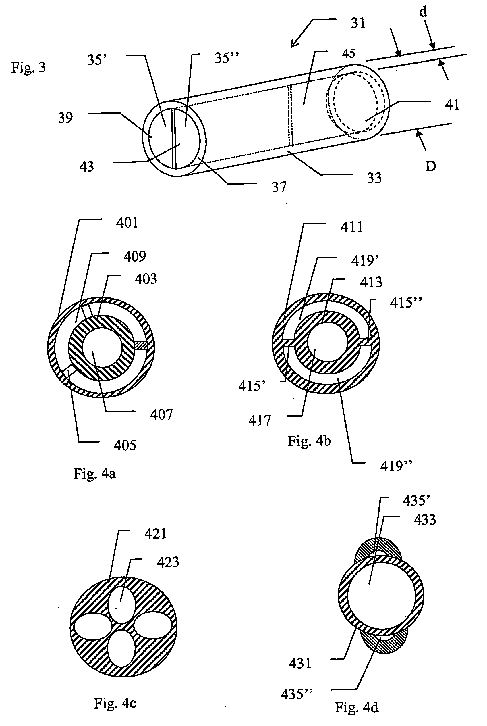
[0053] Examples of possible embodiments of invasive device cross-sections are shown in FIGS. 4a-4d.

[0054]FIG. 4a shows an invasive device formed of two concentric tubes (401, 403) with the inner tube (403) held in place in the centre of the outer tube (401) by an open system of webs (405). A first lumen (407) is formed in the interior of said inner tube and a second lumen (409) is formed by the annular space between the two tubes (401, 403).

[0055]FIG. 4b shows an invasive device formed of two concentric tubes (411,413), with the inner tube (413) held in place in the centre of the outer tube (411) by two continuous webs (415′, 415″). A first lumen (417) is formed in the interior of said inner tube (413) and a second lumen (419′) and a third lumen (419″) are formed by the semi-annular space between the two tubes (411, 413) and the webs (415′, 415″).

[0056]FIG. 4c shows an invasive device comprising an elongated body (421) with four lumens (423) formed in it.

[0057]FIG. 4d shows an i...


PUM


Abstract

The present invention provides methods for passive visualisation of invasive devices by employing a hyperpolarised solution of a high T1 agent having a T1 value of at least 5 seconds at a field strength in the range of 0.001-5 T and a temperature in the range of 20-40° C. Devices and instruments particularly useful for being employed in the methods are also provided as well as use of the methods in imaging, surgery and therapy.

Description

FIELD OF THE INVENTION [0001] The invention relates to magnetic resonance imaging (MRI) of invasive devices, e.g. during surgical and therapeutic procedures, and to devices for use with the procedures. DESCRIPTION OF RELATED ART [0002] Interventional procedures in radiology are very common and increasingly popular. They are normally performed under fluoroscopic feedback by insertion of invasive instruments and / or devices like catheters, guide wires, biopsy needles, etc. through the blood vessels. The procedures can last for several hours and involve very high radiation doses for both the patient and the personnel performing them. During these procedures, it is desirable that the physician is able to locate or guide the invasive devices inserted into the patient's body when these devices are no longer visible. Since soft body parts give very little contrast on X-ray, it is often necessary to use high doses of iodinated contrast agents to localize the devices which in turn may cause p...

Claims


Application Information

Patent Timeline
IPC IPC(8): A61B5/05
CPCA61B5/055A61B5/7289A61K49/06
Inventor AXELSSON, OSKARGOLMAN, KLAESMANSSON, SVENPETERSSON, STEFAN
Owner GE HEALTHCARE AS
Why Eureka
Try Eureka