
Novel vanadium halide redox flow battery

a redox flow battery and vanadium halide technology, applied in the direction of non-aqueous electrolyte cells, indirect fuel cells, cell components, etc., can solve the problems of reducing the life of cell components, causing bromine gas emission, etc., and achieve the effect of avoiding excessive bromine generation

Inactive Publication Date: 2006-08-17
NEWSOUTH INNOVATIONS PTY LTD
View PDF5 Cites 81 Cited by
  • Summary
  • Abstract
  • Description
  • Claims
  • Application Information

AI Technical Summary

Benefits of technology

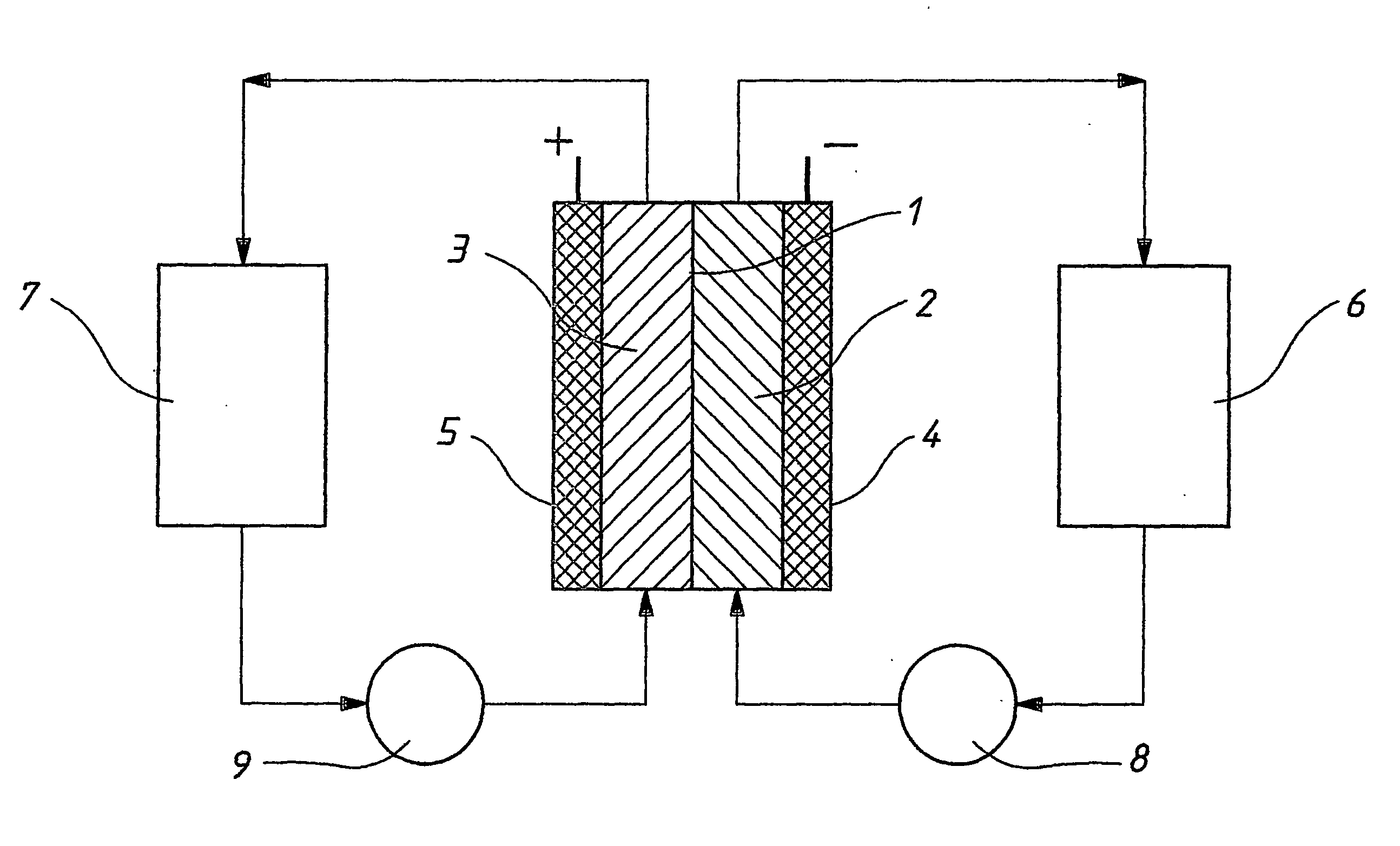
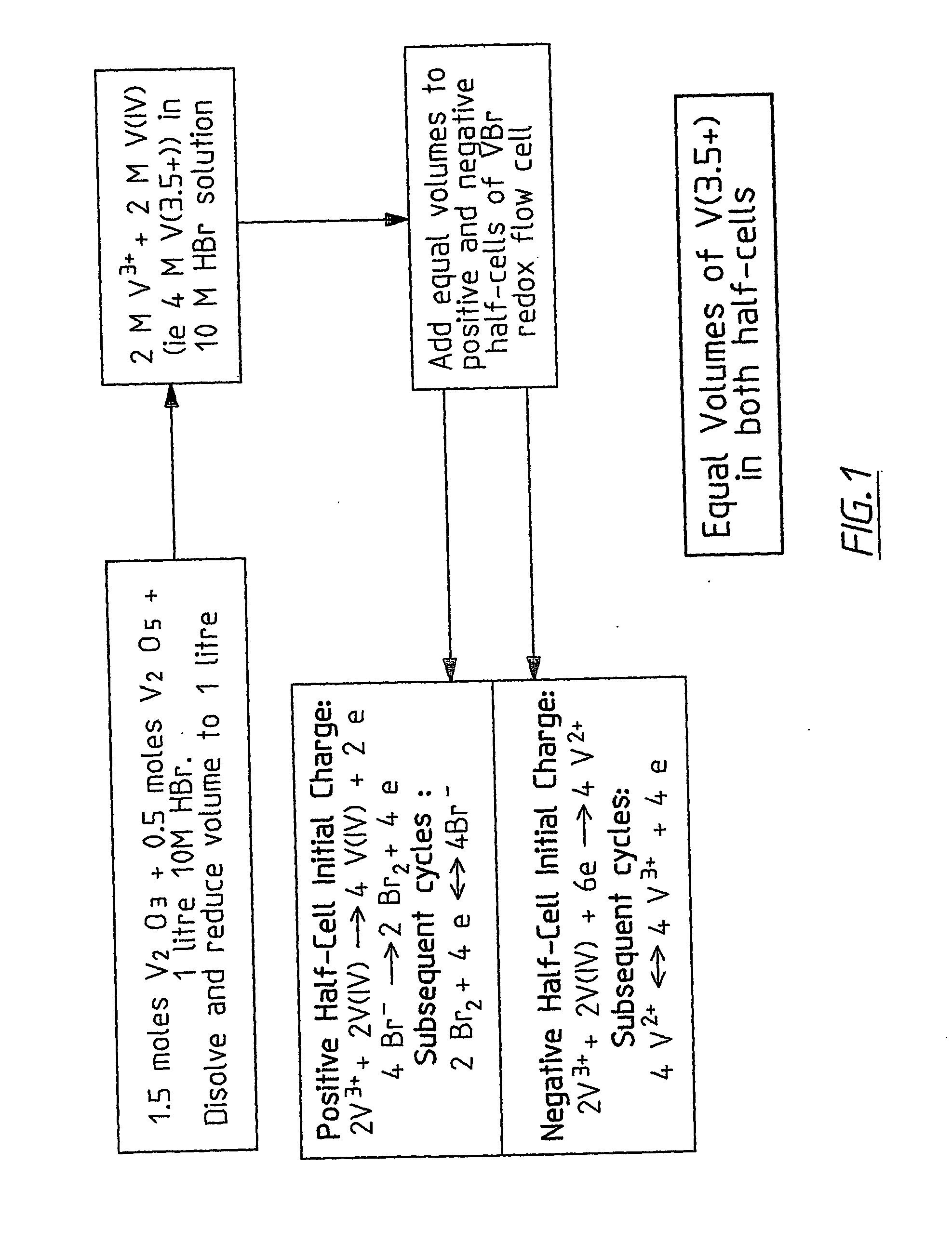
[0053] In a particular form there is provided a method for producing an electrolyte for a vanadium bromide redox cell involving the mixing of a V(III) compound with a V(V) compound in a 3:1 molar ratio in a solution of HBr, NaBr, KBr or mixtures thereof and stirring until fully dissolved to produce an approximately 50:50 mixture of V(III) and V(IV) ions. To avoid excessive bromine generation, the V(III) compound is added to the halide solution first and allowed to partially dissolve before addition of the V(V) compound. The dissolution may be at room temperature or at a temperature ranging from room temperature to boiling temperature. Approximately equal volumes of the solution produced is added to both half-cells of the prior to charge vanadium halide redox cell.
[0087] The V(III) compound may be V203 and the V(V) compound may be V205. To avoid excessive bromine generation, the V(III) compound is added to the halide solution first and allowed to partially dissolve before addition of the V(V) compound. The dissolution may be at room temperature or at a temperature ranging from room temperature to boiling temperature or from room temperature to 80° C.
[0132] The electrolyte can also contain a suitable complexing agent to stabilise the bromine or polyhalide produced during charging of the vanadium halide redox flow cell or redox cell. Complexing the bromine with suitable complexing agents such as polyethylene glycol, tetra-alkyl-ammonium halides such as 2-pyrrolidone, n-methyl pyrrolidone, or ring structures with nitrogen atoms in the ring structure, such as pyrridine compounds, will stabilise the bromine so that more of the bromide ions in solution can be oxidised during charging.
[0133] In a separate embodiment of this invention, a gelled or immobilised vanadium halide redox cell is also disclosed. By immobilising or gelling the vanadium halide cell electrolytes with an immobilising or gelling agent such as silica, fumed silica, fumed alumina, fumed titania or polyacrylamide, it is also possible to stabilise the bromine produced, so that a greater fraction of the bromide ions can be oxidised during charging in the positive half-cell electrolyte.
[0135] The negative and positive electrode materials for the vanadium halide redox flow cell or redox cell may be porous carbon or graphite felt, matte or cloth materials on a graphite, glassy carbon or conducting plastic substrate. The positive electrode material can also be an oxide coated titanium metal sheet or expanded metal mesh. The titanium based electrode would provide greater long term stability against oxidation during charging of the positive half-cell solution. Multiple cells can also be incorporated into a cell stack consisting of bipolar electrodes, these bipolar electrodes comprising carbon or graphite felt, cloth or matte either pressed against or heat welded onto a conducting plastic substrate, this conducting plastic substrate comprising carbon filled polyethylene, polypropylene or other thermoplastic polymer that may also be mixed with a rubber material to impart good mechanical properties. The bipolar electrodes for the vanadium halide redox flow cell or redox cell can also be produced by heat bonding the porous carbon or graphite felt into each side of a polyethylene, polypropylene or other polymer sheet such that the conducting carbon or graphite felt fibres in each side of the insulating substrate contact each other through the plastic sheet, thereby making electrical contact without the need to add a conducting filler to the plastic substrate.
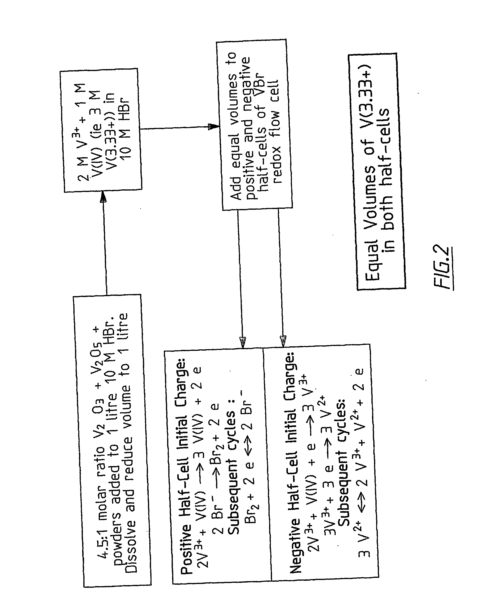
[0137] To discharge the battery, the stack terminals are connected to a load and when the circuit is closed, electricity is produced by the flow of electrons from the negative terminal to the positive terminal of the cell or battery stack. Charging and discharging can be carried out either with the pumps switched on and the electrolytes recirculating through the external tanks and cell stack, or with the pumps off, allowing the solution in the stack itself to undergo discharge reactions. Periodically the two solutions may be remixed to produce the original V(3.5+) or in the case of the high energy density cell, the original V(3.33+) electrolytes in both tanks. This periodic mixing allows any chemistry imbalance arising from the transfer of ions across the membrane to be corrected, so that the capacity of the system can be restored. The periodic mixing can be full or only partial mixing.

Problems solved by technology

This means that the positive half-cell electrolyte always contains excess bromine or the relatively unstable Br3− or Br2Cl− species that could give rise to bromine gas emission problems during operation of the vanadium bromide battery.
Furthermore, the presence of excess bromine in the positive half-cell electrolyte increases the corrosive properties of this solution, reducing the life of the cell components.

Method used


Image

  • Novel vanadium halide redox flow battery
  • Novel vanadium halide redox flow battery
  • Novel vanadium halide redox flow battery

Examples


example 1

[0166]FIG. 6 shows the initial charge-discharge curve for a vanadium halide redox flow cell containing 60 ml in each half-cell of a 2 M V(3.5+) solution in 6 M Br− plus 2 M Cl−. The cell employed a Gore Select P-03430 membrane. The cell was initially charged to a voltage of 1.25 V and discharged to a lower voltage limit of 0.25 V at a constant current of 1.0 Amp. The ratio of the initial charge time to the discharge time is seen to be approximately 1.5 showing that during the initial charge, 1.5 electrons per mole of vanadium are used in converting the V(3.5+) solution to V2+ in the negative half-cell while in the positive half-cell, V(III) ions are first oxidised to V(IV) followed by the oxidation of Br− ions to Br3−. Subsequent charge-discharge cycles gave average charge and discharge time ratios of between 1.05 and 1.1, corresponding to coulombic efficiencies of 95 to 91%.

example 2

[0167] A cell employing a solution of 3 M vanadium (III) / (IV) bromide as the active material in both half-cells was set up and evaluated as follows:

[0168] The 50:50 vanadium(III) / vanadium (IV) bromide mixture (referred to as 3 M V(3.5+) was prepared by dissolving the required amounts of vanadium trioxide and pentoxide powders in 8 M hydrobromic acid. Hydrochloric acid was also added to bring the final solution chloride concentration to 1.5 M.

[0169]FIG. 7 shows the cell voltage versus time curves obtained during the charging and discharging cycling of the cell containing 60.0 mls of the solution in each half-cell and employing a Gore Select P-03430 membrane. The cell was charged to a voltage of 1.6 V and discharged to a lower voltage limit of 0.25 V at a constant current of 2.0 Amp. The theoretical charge and discharge time, assuming complete reaction of the vanadium ions in the negative half-cell was calculated as 2.4 hours. This compares with measured charge and discharge times o...

example 3

[0170] A 3 M V(3.5+) solution was prepared by combining a 3:1 mole ratio of V2O3:V2O5 powders as follows:

[0171] Mass V2O3 used: 168.64 g

[0172] Mass V2O5 used: 62.21 g

[0173] 1000 ml of 8M HBr was mixed with 150 ml 10 M HCl, stirred and heated around to 80° C. The V2O3 powder was slowly added to the HBr / HCl mixture, followed by slow addition of the V2O5 powder. The solution was then boiled to around 150° C. for about 1 hour. The final volume was approximately 1010 ml. During the vanadium oxide dissolution, negligible bromine was detected. When the same process was repeated by simultaneously adding the vanadium trioxide and vanadium pentoxide powders to the HBr / HCl mixture, however, bromine gas was observed to form as the vanadium pentoxide oxidised the bromide ions to bromine.


PUM


Abstract

A prior to charge vanadium halide redox cell, a vanadium halide redox cell which is at a state of charge selected from the group consisting of a zero state of charge and a near zero state of charge and vanadium halide redox cell which are fully charged and partially charged are described. The prior to charge vanadium halide redox cell comprises a positive half cell containing a positive half cell solution comprising a halide electrolyte, vanadium (III) halide and vanadium (IV) halide, a negative half cell containing a negative half cell solution comprising a halide electrolyte, vanadium (III) halide and vanadium (N) halide wherein the amounts of vanadium (III) halide, vanadium (IV) halide and halide ions in the positive and negative half cell solutions are such that in a first charging step comprising charging the prior to charge vanadium halide redox cell, a vanadium halide redox cell having a state of charge selected from the group consisting of a zero state of charge and a near zero state of charge comprising predominantly vanadium (N) halide in the positive half cell solution and predominantly V(III) halide in the negative half cell solution can be prepared. The vanadium halide redox cell which is at a state of charge selected from the group consisting of a zero state of charge and a near zero state of charge comprises a positive half cell containing a positive half cell solution comprising a halide electrolyte and a vanadium halide which is predominantly vanadium (N) halide, a negative half cell containing a negative half cell solution comprising a halide electrolyte and a vanadium halide which is predominantly vanadium (III) halide wherein the amount of vanadium (N) halide in the positive half cell solution and the amount of vanadium (III) halide in the negative half cell solution are such that the vanadium halide redox cell is at a state of charge selected from the group consisting of a zero state of charge and a near zero state of charge. The vanadium halide redox cell which is fully charged comprises a positive half cell containing a positive half cell solution comprising a halide electrolyte, a polyhalide complex, vanadium (IV) halide and vanadium (V) halide, a negative half cell containing a negative half cell solution comprising a halide electrolyte and vanadium (II) halide wherein the molar concentration of vanadium (V) and polyhalide complex:molar concentration of vanadium (II) halide is about stoichiometrically balanced. The vanadium halide redox cell which is partially charged comprises a positive half cell containing a positive half cell solution comprising a halide electrolyte, a polyhalide complex, vanadium (IV) halide and vanadium (V) halide, a negative half cell containing a negative half cell solution comprising a halide electrolyte, vanadium (II) halide and vanadium (III) halide wherein the number of moles of moles of polyhalide complex and vanadium (V): number of moles of vanadium (II) halide is about stoichiometrically balanced.

Description

TECHNICAL FIELD [0001] Disclosed is a vanadium halide redox flow cell employing a 50:50 vanadium(III) / (IV) halide solution as the initial feed electrolyte solution in both the positive and negative half cells. Also disclosed is the 50:50 V(III) / V(IV) halide feed solution for use in the positive and negative half-cells of the vanadium halide redox flow cell. A vanadium halide redox flow cell is also disclosed in which the initial feed solution for the negative half-cell is a vanadium (III) halide electrolyte and in which a vanadium (IV) halide electrolyte is used as feed solution for the positive half-cell. Methods of producing the vanadium (III), vanadium (IV) and vanadium (III) / (IV) halide electrolytes for the vanadium halide redox flow cell are also disclosed. In addition, a method of producing electricity by discharging the fully charged or partially charged vanadium halide redox flow cell or battery is disclosed, as well as methods of recharging the discharged or partially disch...

Claims


Application Information

Patent Timeline
IPC IPC(8): H01M8/20H01M8/18
CPCB60L11/1822B60L11/1879B60L2240/545H01M8/188H01M8/20Y02T90/14Y02T10/7005Y02T10/705Y02T10/7072Y02T90/124Y02E60/528B60L53/80B60L50/64Y02E60/50Y02T10/70Y02T90/12
Inventor KAZACOS, MICHAELSKYLLAS-KAZACOS, MARIAKAZACOS, NICHOLASL
Owner NEWSOUTH INNOVATIONS PTY LTD
Learn More