
System and method to simulate hemodynamics

a system and hemodynamic technology, applied in the field of system and method for simulating the hemodynamic patterns of physiologic blood flow, can solve the problems of reducing blood flow affecting the hemodynamics of the body, so as to reduce the risk of stroke, death, and increase the risk of strok

Inactive Publication Date: 2006-09-21
DANCU MICHAEL B
View PDF4 Cites 25 Cited by
  • Summary
  • Abstract
  • Description
  • Claims
  • Application Information

AI Technical Summary

Benefits of technology

[0035] Another object of the present invention is to provide a system in which the effects of vasoactive compounds can be studied.
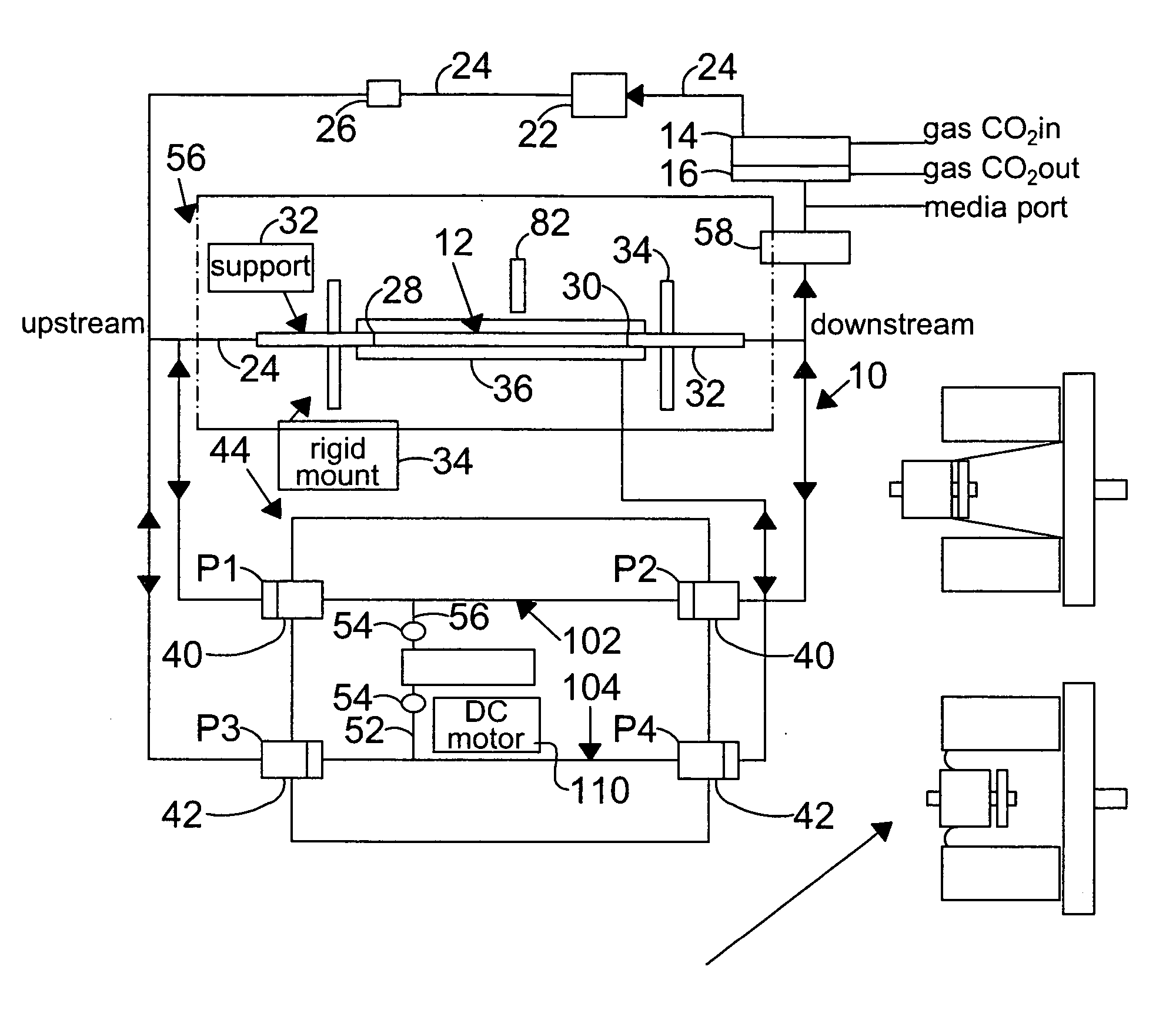
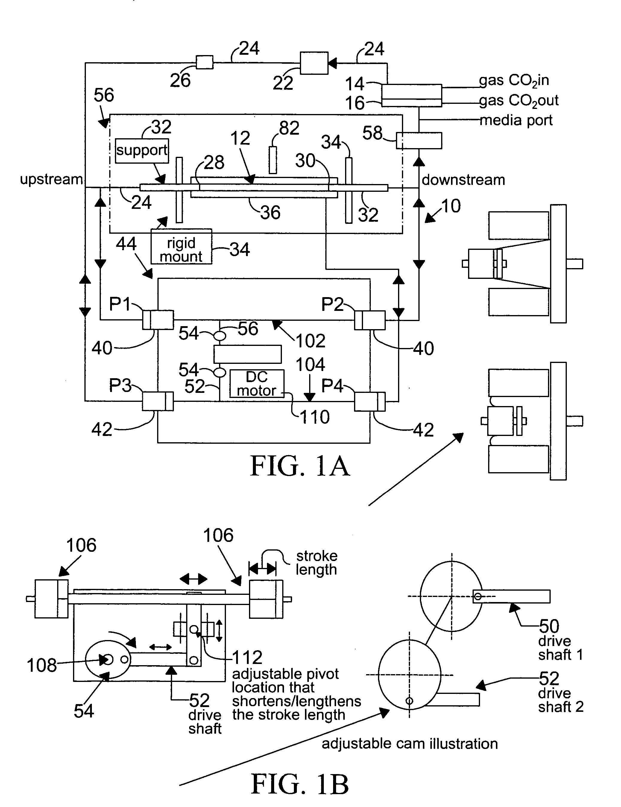
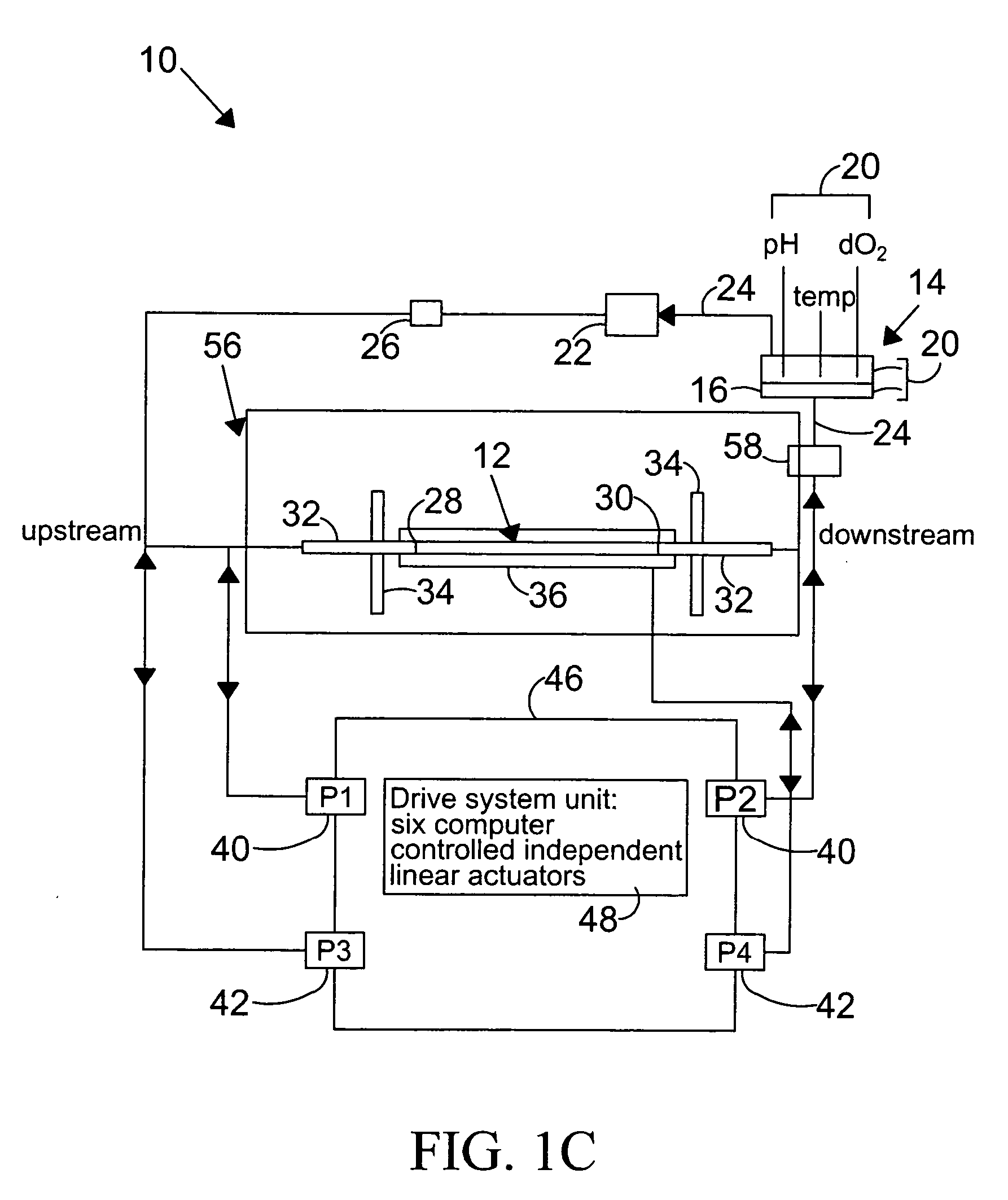
[0050] The present invention achieves the uncoupling of pulsatile flow and pulsatile pressure to provide independent control over WSS and CS. The system at first seems paradoxical since it is classically well known that pressure and flow are coupled. However, in a dynamic sinusoidal environment, such as that of the present invention, flow and pressure can be independently modulated and therefore, appear to be uncoupled. The drive system, comprising two reciprocating drive shafts that are coupled via a circular cam effects this uncoupling. The flow shaft drives pumps, that are at opposite ends, that are 180 degrees out-of-phase and are connected to the recirculating flow loop upstream and downstream of the test section (compliant vessel). The flow shaft allows independent control of pulsatile flow with no pulsatile circumferential strain. The second (pressure) shaft also drives two piston pumps that are 180 degrees out-of-phase; however, one piston drives the internal pressure upstream to the test section and the other piston drives the external chamber pressure. The pressure shaft allows for independent control of the pulsatile pressure. The attachment points of the circular cam that couples the two drive shafts can be adjusted to provide the phase (between 0 and 360 degrees) between the motions of the two shafts. This phase difference provides simulation of a wide range of SPAs, including the disease prone coronary arteries (approximately 250 degrees). Since the flow is related to wall shear stress (WSS) and the pressure is related to the circumferential strain (CS), the pulsatile WSS and pulsatile CS are independent and uncoupled.
[0051] The present invention is a system for hemodynamic simulation comprising a vessel having properties of a blood vessel, a reservoir containing a quantity of fluid, tubing connecting the vessel and reservoir, and at least one pump for circulating the fluid within the system. Fluid can be tissue culture medium or blood analog fluid, and the vessel may include mammalian cells attached to its inside. A drive system, comprising two reciprocating drive shafts that are coupled by a cam, enables the uncoupling of pulsatile flow and pulsatile pressure to provide independent control over wall shear stress and circumferential strain. The shaft drives two pumps that are 180 degrees out-of-phase and are connected upstream and downstream of the vessel, and effect this uncoupling.

Problems solved by technology

Cardiovascular disease is the leading cause of death in the United States, and costs millions of dollars per year.
Atherosclerosis is a disorder in which the coronary arteries become clogged by the build up of plaque along the interior walls of the arteries, leading to decreased blood flow which can in turn cause hypertension, ischemias, strokes and, potentially, death.
A major problem associated with bypass surgery is the patency of the vessels to be used in the bypass.
The bypass vessels are prone to failure, which may occur within a short period of time after bypass surgery, or after a period of several years.
Hemodynamic forces have been implicated as a major factor contributing to the failure of the bypass vessels.
Despite the significance of hemodynamic WSS and CS acting on the vessel wall, especially at regions of the circulation with a high risk of localization of cardiovascular diseases, detailed knowledge of the combined influence of the time varying patterns of WSS and CS on endothelial cell biological response has remained technologically unfeasible.
Qiu and Tarbell described a device to simulate pressure and flow in tubes, but the device did not permit using a wide range of phase angles (SPAs), and was technically difficult to use.
Limitations, however, of the Qiu and Tarbell system included having the maximum attainable phase angle being 100 degrees, the amplitude and phase of the flow and pressure are coupled, and the system utilized large quantities of fluid.
Oscillation of the test vehicle results in the pulsatile movement of fluid over its surface.
These forces may be uniformly applied to the cells, or they may be selectively non-uniformly applied.
The WSS in these devices is usually steady because of difficulties in simulating pulsatile flow.
Both types of systems are thus limited by their design.
However, no studies have been performed studying both parameters (WSS and CS) using cells grown on a single type of support surface because such a system, until now, has remained technologically unfeasible.
However, these tubes were used in flow simulators coupling pressure and flow that could only achieve phase angles (SPAs) of about 90-100 degrees; such a phase angle was inadequate for simulating coronary arteries, the most disease prone vessels in the circulation, because coronary arteries are characterized by a high SPA, on the order of approximately 250 degrees.
These flow simulators were difficult to use and to produce replicable reliable results.

Method used


Image

  • System and method to simulate hemodynamics
  • System and method to simulate hemodynamics
  • System and method to simulate hemodynamics

Examples


example 1

Preparation of Silicone Tubing for Attachment and Growth of Endothelial Cells

[0124] In this example, the vessel chosen for growth of endothelial cells is a silicone tubing, sold by Dow-Coming, Midland, Mich. under the brand name of SYLGARD 184® elastomer, or Silastic (MDX4-4210), Medical Grade tubing, and used to prepare elastic artery models. These models were prepared using the method described by Lee and Tarbell (1997, and hereby incorporated by reference), and included the preparation of models of human linear and bifurcating arteries.

[0125] For the preparation of linear elastic vessels, a pair of symmetric, half-cylindrical grooved molds made of a plastic, such as PLEXIGLASS, are machined to have a diameter that matches the inner diameter of the elastic model described above. In one preferred embodiment, the linear elastic vessels have a length of approximately 29 centimeters and an inner diameter of approximately 0.79 centimeters, in another embodiment of the present inventi...

example 2

Tissue Culture Conditions

[0128] Endothelial cells (“ECs”) were obtained either from bovine aortas (“BAECs”), or from human umbilical veins (“HUVECs”), and cultured by growth as primary cultures, using procedures described in Sill et al. (1995), the contents of which is hereby incorporated by reference.

[0129] The BAECs were the cells most commonly used with the present invention. An inoculum of between 60,000-80,000 cells per square centimeter is used twice, once to enable the cells to adhere to the surface of the vessel for a 45 minute time period, and a second time after rotating the position of the vessel 180 degrees to enable the vessel's other side to become coated. The cells are grown in a monolayer until confluency is achieved, in a 37 degree centrigrade tissue culture incubator in an atmosphere of 5% CO2 in air. The preferred growth medium 16 is Dulbecco's Modified Eagle's Medium (“DMEM”, obtained commercially from Sigma Chemical Corp., St. Louis, Mos.), containing 10% Feta...

example 3

Effect of Different Stress Phase Angles: Zero Degree SPA

[0132]FIG. 2 is a plot of the diameter (circles) and pressure (triangles) waveforms as a function of time with a zero degree stress phase angle (SPA) difference.

[0133] Changes in the diameter of the compliant vessel 12 can be measured by one of several methods known to those skilled in the art. These include the use of such non-contacting methods as ultrasound or laser light, or the use of an elastic strain gauge, which is in physical contact with the specimen (the compliant vessel). In the present invention, the preferred method of monitoring the changes in compliant vessel diameter is with an ultrasound transducer (Panametrics Co., not shown) which is mounted through the exterior chamber wall and which is focused on the compliant vessel.

[0134] The computer controlled drive unit 44 is capable of generating different waveforms, which can range from a sine wave, as employed in this and the subsequent examples (FIGS. 2-6), or ...


PUM

PropertyMeasurementUnit
phase angleaaaaaaaaaa
phase anglesaaaaaaaaaa
stress phase angleaaaaaaaaaa

Abstract

A system for hemodynamic simulation comprises a vessel having properties of a blood vessel, a reservoir containing a quantity of fluid, tubing connecting the vessel and reservoir, and at least one pump for circulating the fluid within the system. Fluid can be tissue culture medium or blood analog fluid, and the vessel may include mammalian cells attached to its inside. A drive system, comprising two reciprocating drive shafts that are coupled by a cam, enables the uncoupling of pulsatile flow and pulsatile pressure to provide independent control over wall shear stress and circumferential strain. The shaft drives two pumps that are 180 degrees out-of-phase and are connected upstream and downstream of the vessel, and effect this uncoupling.

Description

CROSS-REFERENCE TO RELATED APPLICATIONS [0001] This application is a Continuation of U.S. application Ser. No. 09 / 973,433, filed Oct. 9, 2001, which claims the benefit of U.S. Provisional Application No. 60 / 239,015, filed Oct. 6, 2000. The entire disclosure of the prior applications are considered as being part of the disclosure of the accompanying application and is hereby incorporated by reference therein.STATEMENT REGARDING FEDERALLY SPONSORED RESEARCH OR DEVELOPMENT [0002] The work described in this application was supported by funding from the National Institutes of Health under Grant No. HL-35549. The United States Government may have certain rights to the invention.FIELD OF THE INVENTION [0003] The present invention is a system and method for simulating the hemodynamic patterns of physiologic blood flow. In particular, the present invention can simultaneously generate wall shear stress and circumferential strain patterns relevant to cardiovascular function and disease. BACKGR...

Claims


Application Information

Patent Timeline
Patent Type & Authority Applications(United States)
IPC IPC(8): A01N1/02C12M3/00C12M1/36G09B23/28
CPCG09B23/28Y10S623/921Y10S623/917Y10S623/916
Inventor DANCU, MICHAEL B.TARBELL, JOHN M.
Owner DANCU MICHAEL B
Learn More