
Anisotropic conductive connector, conductive paste composition, probe member, wafer inspection device and wafer inspection method

a technology of conductive paste composition and conductive connector, which is applied in the direction of coupling device connection, semiconductor/solid-state device details, instruments, etc., can solve the problems of a large number of integrated circuit devices that take a long time to individually conduct electrical inspection, and the conductivity of conductive parts thereof has been markedly deteriorated, etc., to achieve high conductivity, long service life, and high durability

Active Publication Date: 2006-09-21
ISC CO LTD
View PDF9 Cites 11 Cited by
  • Summary
  • Abstract
  • Description
  • Claims
  • Application Information

AI Technical Summary

Benefits of technology

[0047] According to the anisotropically conductive connectors of the present invention, the conductive particles contained in the conductive parts for connection in the elastic anisotropically conductive films are obtained by forming a coating layer having a high hardness, for example, a Vickers hardness (Hv) of at least 40, so that occurrence of separation, abrasion, deformation and / or the like on the coating layer in the conductive particles by contact between the conductive particles, and the like is inhibited even when they are used repeatedly over a great number of times in electrical inspection of, for example, integrated circuits formed on wafer. As a result, necessary conductivity is retained over a long period of time, and thus high durability and long service life are achieved.
[0048] The coating layer is formed of gold and another high-conductive metal, whereby conductive parts for connection having high conductivity are obtained, and moreover the surfaces of the conductive particles are inhibited from being deteriorated even when the anisotropically conductive connector is used repeatedly over a great number of times under a high-temperature environment. As a result, necessary conductivity is retained over a long period of time, and thus high durability and long service life are achieved.
[0049] The frame plate for supporting the elastic anisotropically conductive films is provided, whereby the anisotropically conductive connectors are hard to be deformed and easy to handle, and the positioning and the holding and fixing to a wafer can be easily conducted in an electrically connecting operation to the wafer.
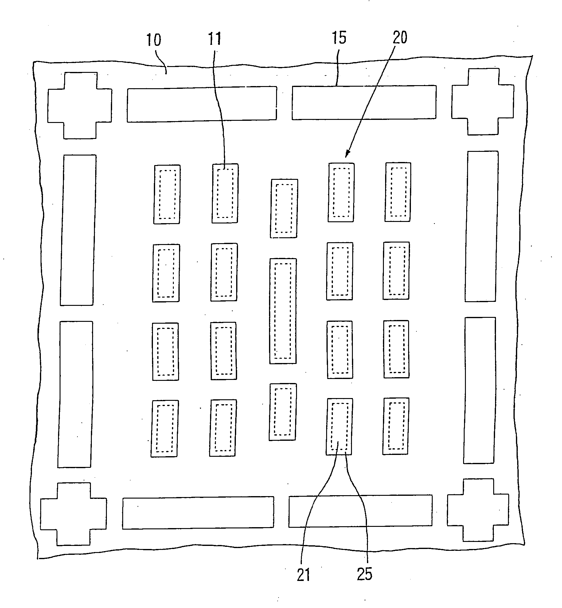
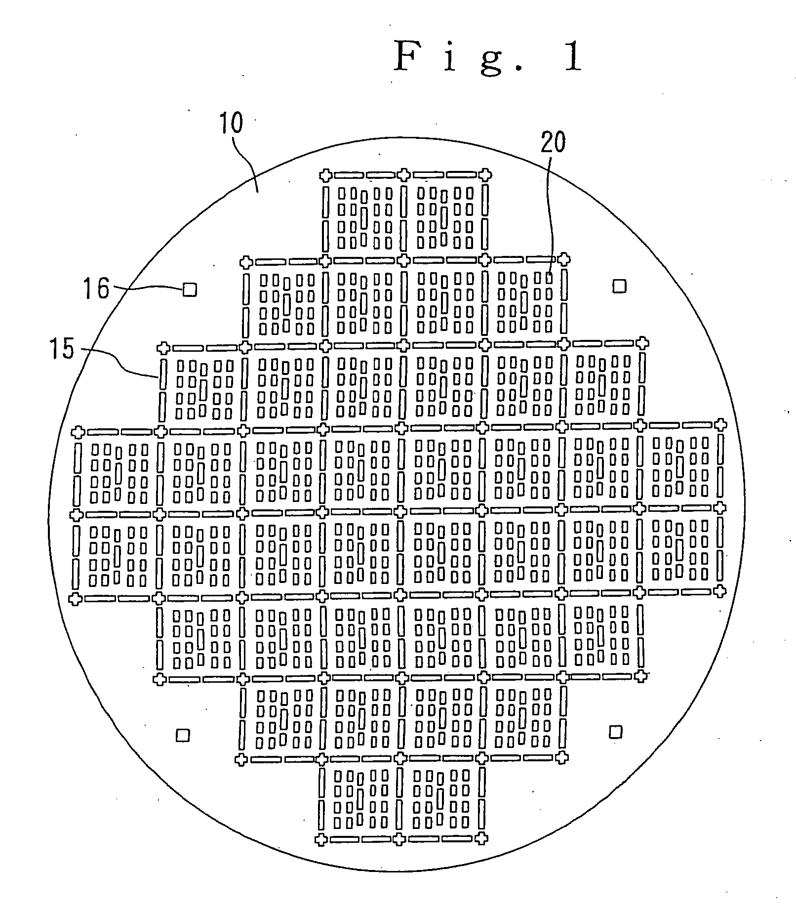
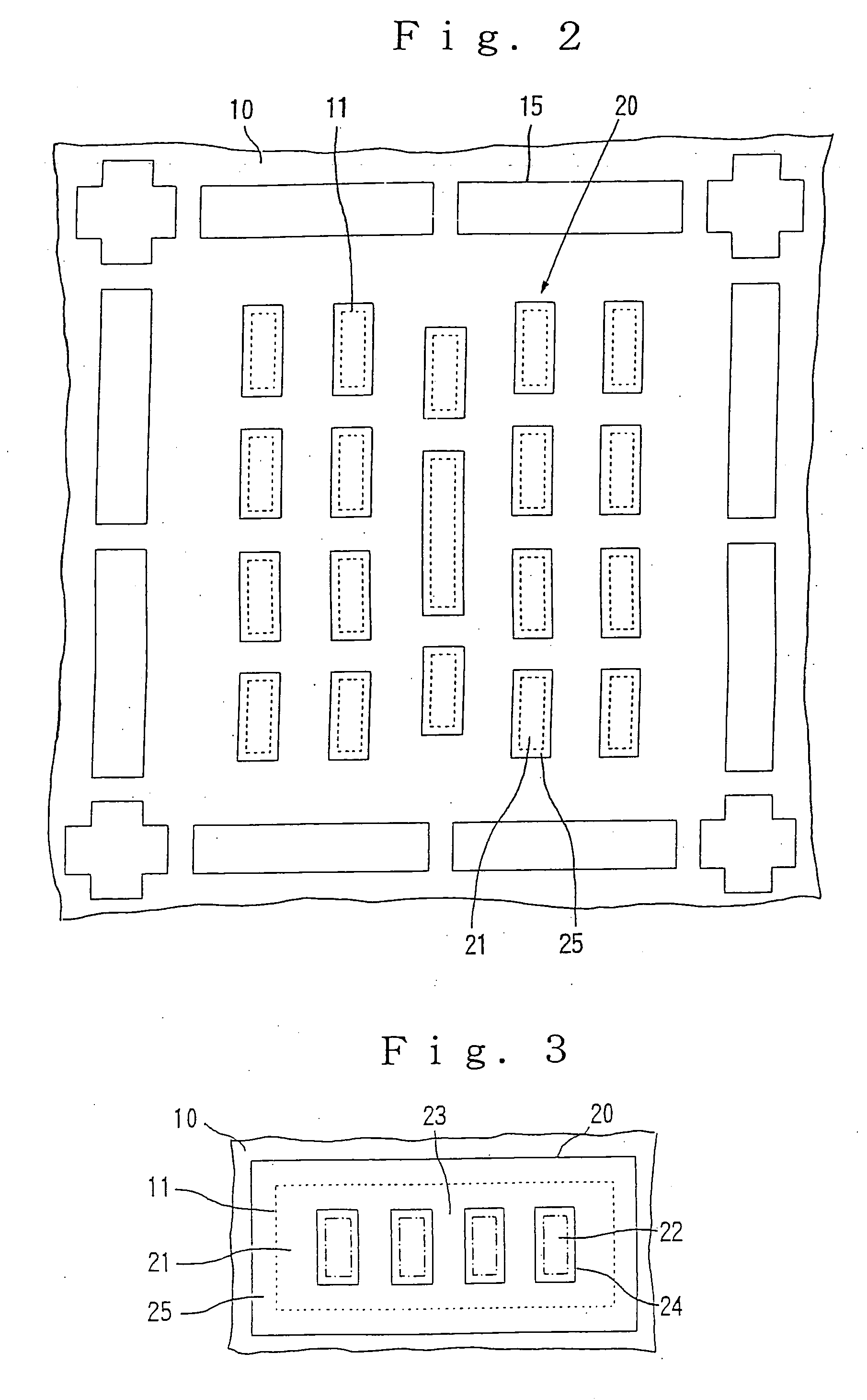
[0050] Since a frame plate, in which a plurality of anisotropically conductive film-arranging holes have been formed corresponding to electrode regions, in which electrodes to be inspected have been formed, of integrated circuits in a wafer, which is an object of inspection, is used as the frame plate, whereby the elastic anisotropically conductive film arranged in each of the anisotropically conductive film-arranging holes of the frame plate may be small in area, the individual elastic anisotropically conductive films are easy to be formed. In addition, since the elastic anisotropically conductive film small in area is little in the absolute quantity of thermal expansion in a plane direction of the elastic anisotropically conductive film even when it is subjected to thermal hysteresis, the thermal expansion of the elastic anisotropically conductive film in the plane direction is surely restrained by the frame plate by using a material having a low coefficient of linear thermal expansion as that for forming the frame plate. Accordingly, a good electrically connected state can be stably retained even when the probe test or wafer level burn-in test is performed on a large-area wafer.
[0051] According to the conductive paste composition of the present invention, the elastic anisotropically conductive films in the above-described anisotropically conductive connectors can be advantageously formed.
[0052] Since the probe members according to the present invention are equipped with any of the above-described anisotropically conductive connectors, good conductivity is retained over a long period of time even when they are used repeatedly over a great number of times, and thus high durability and long service life are achieved.

Problems solved by technology

In a conventional anisotropically conductive elastomer sheet, however, the conductivity of conductive parts thereof has been markedly deteriorated when it has been used in the probe test repeatedly, for example, 20,000 times or more, so that it has been unable to be used in subsequent tests, and so it has been required to be replaced by new one.
In a burn-in test on the other hand, it takes a long time to individually conduct electrical inspection of a great number of integrated circuit devices because each integrated circuit device, which is an object of inspection, is fine, and its handling is inconvenient, whereby inspection cost becomes considerably high.
In a conventional anisotropically conductive elastomer sheet, however, the conductivity of conductive parts thereof has been markedly deteriorated when it has been used in the WLBI test repeatedly, for example, 200 times or more, so that it has been unable to be used in subsequent tests, and so it has been required to be replaced by new one.
In a conventional anisotropically conductive elastomer sheet, however, the conductivity of conductive parts thereof has been markedly deteriorated when it has been used in the probe test of wafers having projected electrodes to be inspected repeatedly, for example, 10,000 times or more, so that it has been unable to be used in subsequent tests, and so it has been required to be replaced by new one.

Method used


Image

  • Anisotropic conductive connector, conductive paste composition, probe member, wafer inspection device and wafer inspection method
  • Anisotropic conductive connector, conductive paste composition, probe member, wafer inspection device and wafer inspection method
  • Anisotropic conductive connector, conductive paste composition, probe member, wafer inspection device and wafer inspection method

Examples


preparation example 1

Of Conductive Particles

(1) Surface Oxide Film-Removing Treatment for Magnetic Core Particles:

[0267] Into a powder treating vessel, were poured 100 g of Magnetic Core Particles [A], and 2 L of 3.2 N hydrochloric acid was added. The resultant mixture was stirred to obtain a slurry containing Magnetic Core Particles [A]. This slurry was stirred at ordinary temperature for 30 minutes, thereby conducting a surface oxide film-removing treatment for Magnetic Core Particles [A]. Thereafter, the slurry thus treated was left at rest for 1 minute to precipitate Magnetic Core Particles [A], and a supernatant was removed.

[0268] To Magnetic Core Particles [A] subjected to the surface oxide film-removing treatment, were added 2 L of purified water, and the mixture was stirred at ordinary temperature for 2 minutes. The mixture was then left at rest for 1 minute to precipitate Magnetic Core Particles [A], and a supernatant was removed. This process was further conducted repeatedly twice, thereby...

preparation example 2

Of Conductive Particles

[0276] Magnetic Core Particles [A] were subjected to a surface oxide film-removing treatment and a surface-washing treatment in the same manner as in Preparation Example 1 of conductive particles. Thereafter, a drying treatment of the particles was conducted by means of a vacuum drier under conditions of 150° C., 1×10⁻³ Pa and 10 hours. Magnetic Core Particles [A] thus treated were then poured into a treating vessel of a powder sputtering apparatus (manufactured by NISSHIN STEEL CO., LTD.), and a target composed of gold was set. Thereafter, air within the treating vessel was evacuated to an atmospheric pressure of 1×10⁻³ Pa while stirring Magnetic Core Particles [A], and argon gas was introduced into the treating vessel so as to give an atmospheric pressure of 1×10⁻¹ Pa. In this state, Magnetic Core Particle [A] were subjected to a sputtering treatment, thereby preparing intermediate particles with a coating layer composed of gold formed.

[0277] After the int...

preparation example 3

Of Conductive Particles

[0282] Conductive particles were obtained in the same manner as in Preparation Example 2 of conductive particles except that a target composed of silver was used in place of the target composed of gold in Preparation Example 2 of conductive particles. The conductive particles will hereinafter be referred to as “Conductive Particles [A3]”.

[0283] Conductive Particles [A3] thus obtained were such that the number average particle diameter was 9.1 μm, the BET specific surface area of 0.35×10³ m2 / kg, the thickness of the intermediate coating layer was 37 nm, the thickness of the surface coating layer was 20 nm (total thickness of the coating layers: 57 nm), the proportion of the intermediate coating layer to Magnetic Core Particles [A] was 15% by mass, the proportion of the surface coating layer to Magnetic Core Particles [A] was 10% by mass (total proportion of the coating layers: 25% by mass), and the electric resistance value R was 0.08 Ω. Further, the Vickers ...


PUM


Abstract

Disclosed herein are an anisotropically conductive connector, by which good conductivity is retained over a long period of time even when it is used in electrical inspection of a plurality of integrated circuits formed on a wafer repeatedly over a great number of times, and thus high durability and long service life are achieved, and applications thereof. The anisotropically conductive connector of the invention comprises elastic anisotropically conductive films, in each of which a plurality of conductive parts for connection containing conductive particles and extending in a thickness-wise direction of the film have been formed. The conductive particles contained in the conductive parts for connection in the anisotropically conductive connector are obtained by laminating surfaces of core particles exhibiting magnetism with a coating layer formed of a high-conductive metal, and the coating layer is a coating layer having a high hardness.

Description

TECHNICAL FIELD [0001] The present invention relates to an anisotropically conductive connector suitable for use in conducting electrical inspection of printed circuit boards, integrated circuit devices, integrated circuits formed on a wafer, liquid crystal panels, in which circuits have been formed, etc., a conductive paste composition for obtaining this anisotropically conductive connector, a probe member equipped with this anisotropically conductive connector, a wafer inspection apparatus equipped with this probe member, and a wafer inspection method using this probe member, and particularly to an anisotropically conductive connector suitable for use in conducting electrical inspection, such as a probe test or a burn-in test, as to integrated circuits formed on a wafer, a conductive paste composition for obtaining this anisotropically conductive connector, a probe member equipped with this anisotropically conductive connector, a wafer inspection apparatus equipped with this probe...

Claims


Application Information

Patent Timeline
IPC IPC(8): H01R4/58G01R1/073H01L23/498H01R13/24
CPCG01R1/0735H01L23/49827H01R13/2414H01L2924/0002H01L2924/00H01R11/01H01L22/00
Inventor IGARASHI, HISAOSATO, KATSUMIINOUE, KAZUO
Owner ISC CO LTD
Learn More