Modified high-efficiency phase shift modulation method

a phase shift modulation and high-efficiency technology, applied in pulse techniques, single output arrangements, instruments, etc., can solve the problems of increasing the stress increasing large heat sinks, so as to reduce the power loss of the power switch, reduce the emis of electromagnetic interference of the inverter, and improve the conversion efficiency of the inverter

Inactive Publication Date: 2006-10-05
CHANG GUNG UNIVERSITY
View PDF1 Cites 38 Cited by
  • Summary
  • Abstract
  • Description
  • Claims
  • Application Information

AI Technical Summary

Benefits of technology

[0015] It is, therefore, an object of the present invention to provide a modified high-efficiency phase-shift single-phase full-bridge inverter, in which a phase shift is introduced to a gate control signal for a power transistor provided on a diagonal line by a phase shift modulation method so as to achieve purpose of soft switching of the power transistor. As such, power loss of the power switch may be reduced and thus an unnecessary resonant snubber circuit may be eliminated, conversion efficiency of the inverter may be improved, and electromagnetic interferences (EMIs) of the inverter may be reduced and thus switching frequency of the power switch may be increased.

Problems solved by technology

When a hard switching manner is used, a power transistor in the inverter will have a greater switching loss as switching frequency thereof increases, resulting in a greater power loss.
In this case, a considerable large heat sink is required for heat removing.
On the other side, when the switch is turned on, a current pulse greater than a normal current ISLP is arisen at an instant after the switch is turned on due to an output capacitor of the switching device, resulting in an increase stress of the power switch.
Therefore, a power loss is caused during the time period tr.
On the other hand, when the power switch is cut off, a voltage drop between the power switch thereof increases abruptly and a voltage spike is generated.
However, since the current IDS of the power switch has not decreased down to zero at this time, a lower loss is also resulted during the time period tf when the power switch is cut off.
Since the series resonance manner is used to obtain the result of zero current switching, a main limitation of the corresponding configuration lies in that the switching frequency may not be higher than the resonance frequency.
Further, regulation of the output voltage or current of the inverter may become worse when resonance frequency of the power switch shifts owing to aging or production inconsistency of the power device occurred.
In the case of a large load variation occurred, this kind of soft switching techniques will perform poorer.
Further, performance of this method is dependent on the resonant inductance and it is difficult to achieve the purpose of zero voltage switching for some inductance values.
In addition, this method is not suitable to be used where an inductance load is used at an output of such as a motor-driven control.
However, a passive resonant snubber is necessary and complexity of the circuit is increased.
However, an auxiliary switch and a resonant circuit comprising passive devices for resonance are required to be additionally provided, increasing relatively the cost of the inverter.
In addition, control timing for the auxiliary switch of such configuration has to be particularly designed, increasing complexity of the associated circuit.
A disadvantage of such configuration is that the switch has to endure the AC voltage and the output may not be applied with the commonly used pulse width modulation method but requires to be processed by means of discrete pulse modulation (DPM).
In achieving this purpose, the auxiliary switch has to be additionally provided, which requires more complex control timings.

Method used


Image

  • Modified high-efficiency phase shift modulation method
  • Modified high-efficiency phase shift modulation method
  • Modified high-efficiency phase shift modulation method

Examples


examples

[0056] Assuming T=1000 and Duty Cycle=100

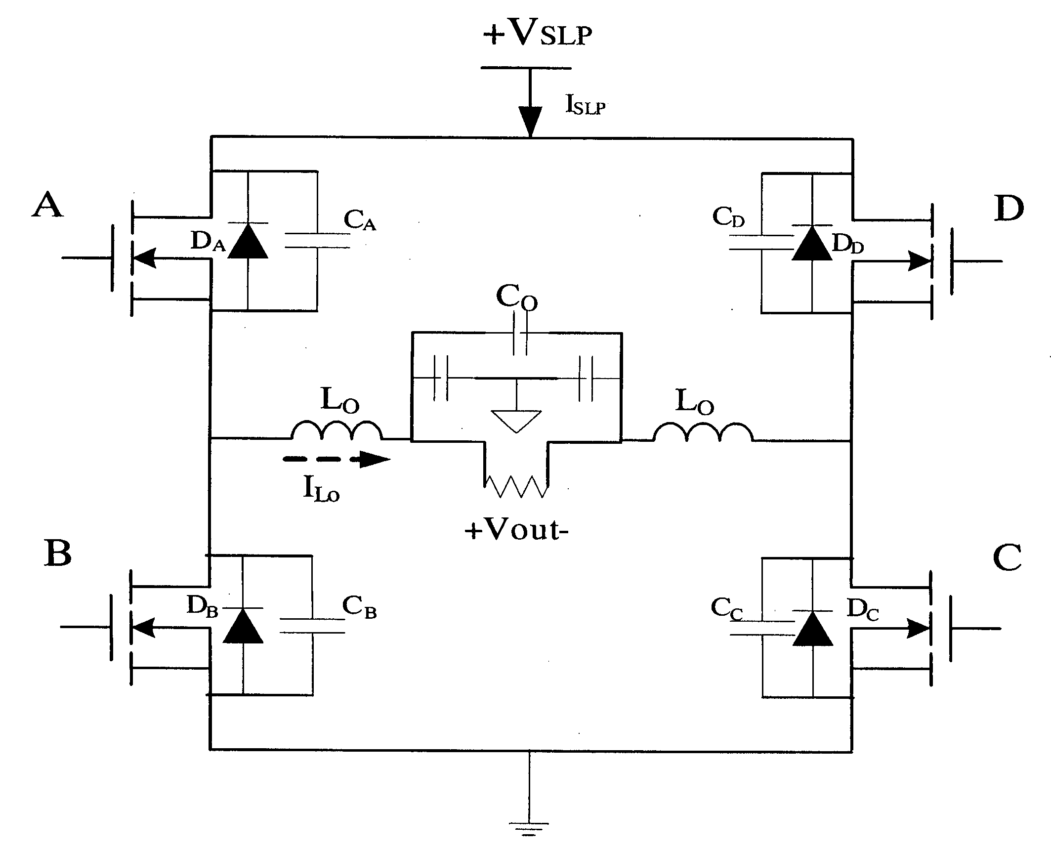
[0057] In a cycle T, the switching device A is set to be “H” for ½T and “L” for ½T. The switching device A has an output inverse to that of the switching device B.

[0058] In a ½T period for the switching device C, 20% in 0-500 (0˜100) is “H” and 80% (101˜500) is “L”. Within the range of 501-1000, 80% (501-900) is “L” owing to duty cycle=100 and 20% (901-1000) is “H”. The switching device D has an inverse output as compared to that of the switching device C.

[0059] Several examples will be described over relationship between duty cycles and the corresponding output waves. [0060] (1) Duty cycle=0.8. The corresponding output waveform is shown in FIG. 17. [0061] (2) Duty cycle=0.6. The corresponding output waveform is shown in FIG. 18. [0062] (3) Duty cycle=0.4. The corresponding output waveform is shown in FIG. 19. [0063] (4) Duty cycle=0.2. The corresponding output waveform is shown in FIG. 20.

[0064] It may be known through the examples given...


PUM


Abstract

Disclosed is a high-efficiency phase shift modulation method suitable for use in a traditional DC/AC single-phase full-bridge inverter. In this method, phase-shifted signal timing is used to modulate a duty cycle so that a power transistor is operated in a zero voltage switching state. As such, noises and switching loss of a switching device when turned on or off, may be reduced and thus efficiency of the inverter may be promoted. With this high-efficiency phase shift modulation method, at least the following advantages may be achieved: lower switching stresses, lower switching losses and thus increased conversion efficiency, lower electromagnetic interferences (EMIs) and no additional circuit required and thus easier realization of a controller for the inverter.

Description

BACKGROUND OF THE INVENTION [0001] 1. Field of Invention [0002] The present invention is related to a traditional DC-AC single-phase full-bridge inverter. Particularly, the present invention is related to a method of operating a switching device in an inverter in a soft switching mode so as to promote efficiency of an inverter, reduce a rating value required for the switching device, reduce electromagnetic interferences caused by switching operations on the switching device and increase switching frequency of the switching device. [0003] 2. Related Art [0004] With rapid development of semiconductor technology used in integrated circuits, electronic products are marching to have the features of slightness and compactness. For a current high efficiency inverter, it typically has an operating frequency of over than 20 kHz so as to stay away from an audio frequency band. When a hard switching manner is used, a power transistor in the inverter will have a greater switching loss as switch...

Claims


Application Information

Patent Timeline
Patent Type & Authority Applications(United States)
IPC IPC(8): H02M3/335
CPCH02M7/53871Y02B70/1441H02M2007/53878H02M2007/4815H02M7/4815H02M7/53878Y02B70/10
Inventor LIU, YI-HWA
Owner CHANG GUNG UNIVERSITY
Why Eureka
Try Eureka