Water management in monopolar fuel cells

a fuel cell and monopolar technology, applied in the field of monopolar fuel cells and monopolar fuel cells, can solve the problems of limited thinness of flexible organic polymer ion exchange membranes used as solid polymer electrolytes in fuel cells, limited membrane drying effect of fuel cells, and increased sensitivity of fuel cells to external elements, etc., to achieve the effect of reducing the number of fuel cell ions

Inactive Publication Date: 2006-10-12
LYNNTECH
View PDF0 Cites 70 Cited by
  • Summary
  • Abstract
  • Description
  • Claims
  • Application Information

AI Technical Summary

Problems solved by technology

In general, thin, flexible organic polymer ion exchange membranes used as solid polymer electrolytes in fuel cells are limited to operating temperatures of less than 100° C. at pressures close to atmospheric pressure since ion conduction through these membranes requires that the membranes be at least partially saturated with water in the liquid phase.
Furthermore, membrane drying effects arising from this mechanism will tend to be non-uniform in the plane of the membrane and will be more pronounced at the points of introduction of the reactant gas(es) into or across the fuel cell.
While the PEM, or at least the anode electrocatalyst / membrane interface, is subject to drying the cathode electrocatalyst / membrane interface can be the subject of flooding.
For a PEM fuel cell, if insufficient water is returned to the anode electrode, adjacent portions of the PEM electrolyte dry out thereby decreasing the rate at which protons may be transferred through the PEM and also resulting in cross-over of the reducing fuel gas, which is typically hydrogen or a hydrogen rich gas, leading to local over heating.
Thus, drying out or localized loss of water can ultimately result in the development of cracks and / or holes in a proton exchange membrane.
These holes allow the mixing of the hydrogen and oxygen reactants, commonly called “cross over,” with a resultant chemical combustion of cross over reactants, loss of electrochemical energy efficiency, and localized heating.
Similarly, if insufficient water is removed from the cathode, the cathode electrode may become flooded effectively limiting oxidant supply to the cathode electrocatalyst and hence decreasing electronic current flow.
Additionally, if too much water is removed from the cathode by the oxidant gas stream, the cathode may dry out limiting the ability of protons to pass through the PEM, thus decreasing cell performance.
This approach has a disadvantage in that it requires that the oxidant gas surrounding the cathode be unsaturated and, preferably, have a low relative humidity, so that the product water (and any water dragged from the anode to the cathode) will evaporate into the unsaturated oxidant gas stream.
However, monopolar fuel cell systems typically do not control the oxidant flow rate or humidity.
This liquid water will prevent access of oxidant gas to the active sites of the cathode electrocatalyst thereby causing an increase in cell polarization, i.e., mass transport polarization, and a decrease in fuel cell performance and efficiency.
Another disadvantage with the removal of product and drag water by evaporation through the use of an unsaturated oxidant gas stream is that the proton conducting membrane itself may become dry under certain operating conditions.
However, this technique has its drawbacks.
For example, high reactant gas flow rates may require a significant consumption of energy, thereby reducing the overall efficiency of the fuel cell system.
Still further, the complexity or efficiency of some fuel cell designs has not been optimized.

Method used


Image

  • Water management in monopolar fuel cells
  • Water management in monopolar fuel cells
  • Water management in monopolar fuel cells

Examples


example 1

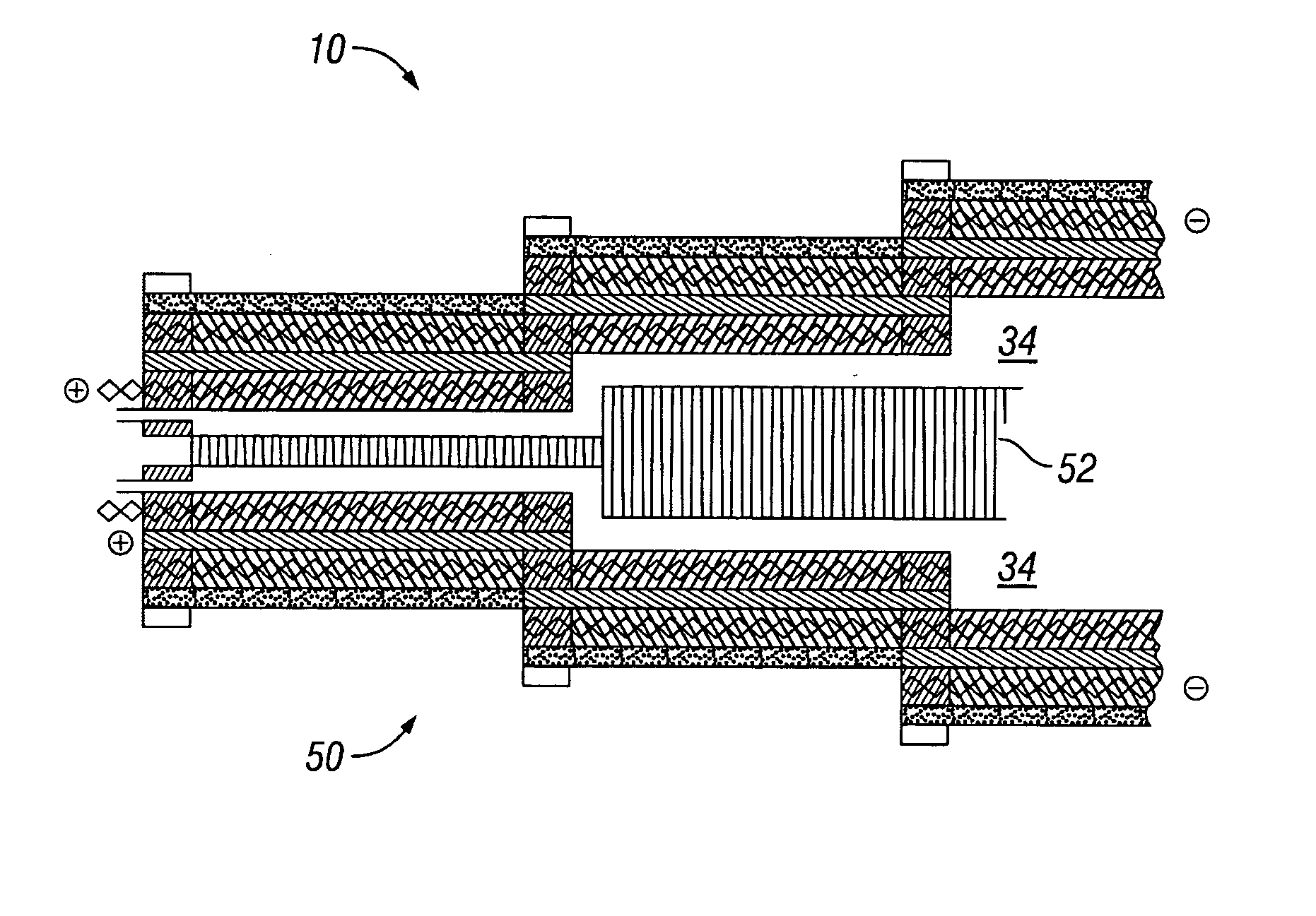
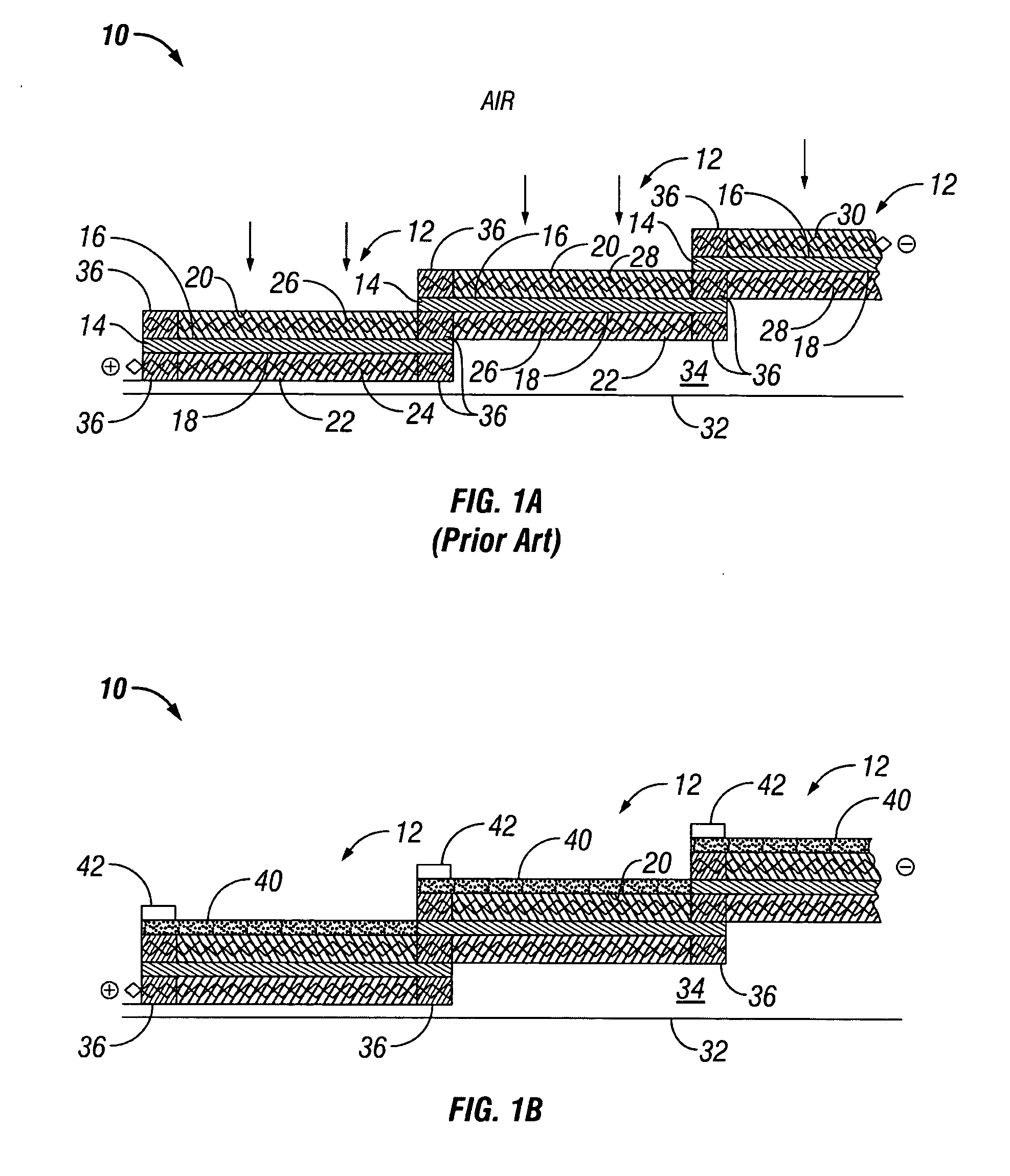
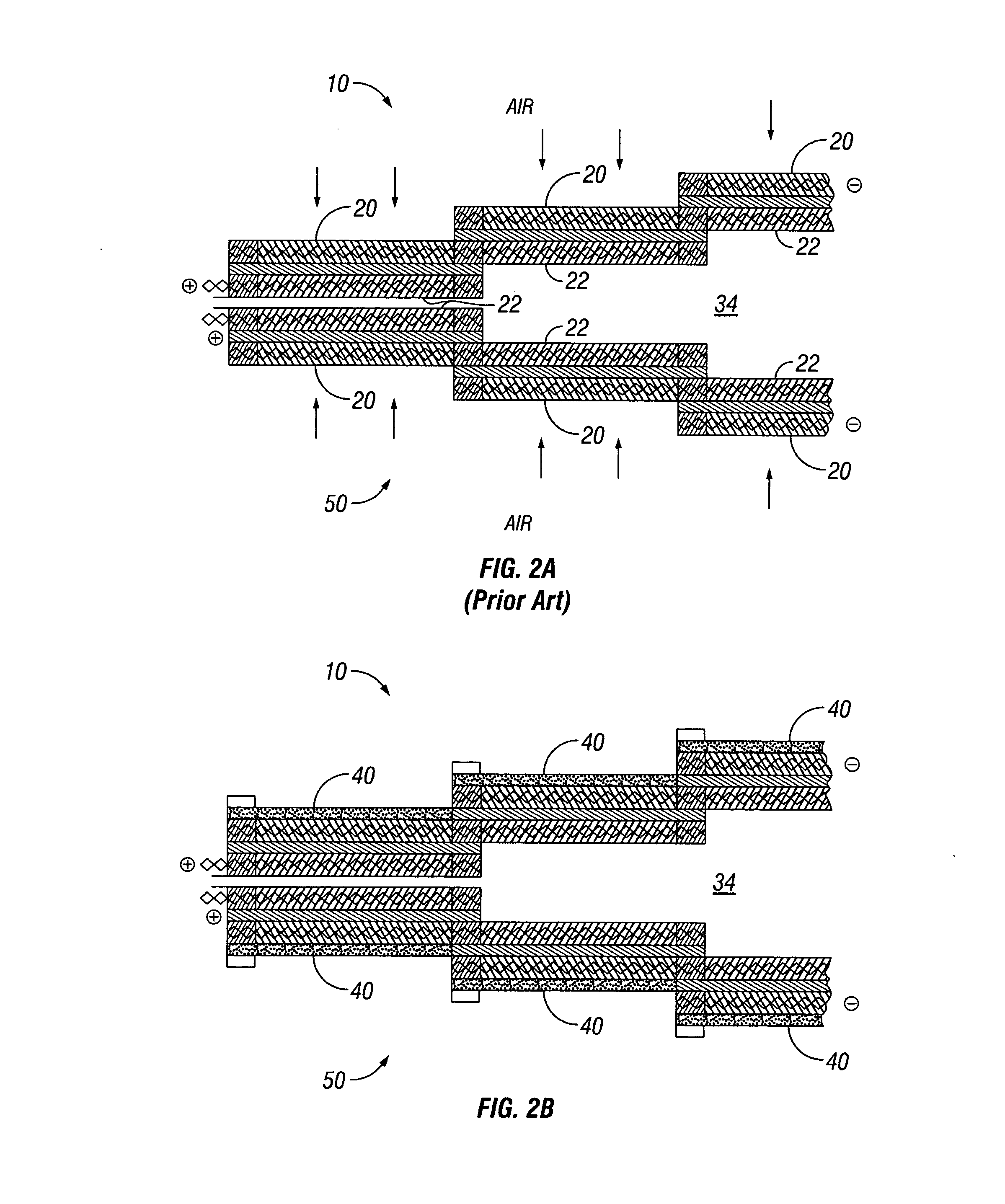
[0087] Two identical five-cell, monopolar fuel cell stacks, similar to that shown in FIG. 3(a), were fabricated. Each stack was constructed with identical components including Nafion® 112 membranes as the PEM electrolyte, Pt black for both the anode and cathode electrocatalysts, and a reactively cured gas diffusion layer applied to a gold plated expanded titanium grid current collector for both the anode and cathode. One of the fuel cell stacks was modified with the addition of a porous liquid water retention barrier covering the entire five-cell cathode surface, similar to that shown in FIG. 3(b). The barrier was secured to the fuel cell along the entire perimeter of the stack to prevent any entry of reactants or exit of products from bypassing the barrier. The barrier used was electronically insulating (electronically non-conducting) and consisted of a sheet of expanded polytetrafluoroethylene (PTFE). The pore size of the barrier was between 35 and 50 nanometers. The sheet was att...

example 2

[0089] The two monopolar fuel cell stacks described in Example 1 were operated as described there. After an initial warming up period, both stacks were held at a constant 1.5 Amps of current. The ambient room temperature was about 25° C. After about three hours the ambient temperature was raised from 25 to 42° C. Initially the performance of both stacks was stable, but eventually the performance of the stack without the porous liquid water retention barrier began to decline, as the proton exchange membrane began to dry out. The performance of the stack with the porous liquid water retention barrier remained steady, as shown in FIG. 8.

example 3

[0090] While the monopolar fuel cell stacks described in Example 1 were operating at 25° C., all of the liquid water found in the exiting fuel stream was collected. This was used as a gauge of the amount of water returned from the cathode to the anode as a result of back diffusion though the proton exchange membrane solid polymer electrolyte. It was observed that the stack with the added porous barrier produced substantially more liquid water at the anode. This further demonstrates the effectiveness of the barrier for retaining water within the cell.

[0091] The terms “comprising,”“including,” and “having,” as used in the claims and specification herein, shall be considered as indicating an open group that may include other elements not specified. The term “consisting essentially of,” as used in the claims and specification herein, shall be considered as indicating a partially open group that may include other elements not specified, so long as those other elements do not materially ...


PUM

PropertyMeasurementUnit
pore sizeaaaaaaaaaa
pore sizeaaaaaaaaaa
thicknessesaaaaaaaaaa

Abstract

A monopolar fuel cell stack comprising proton exchange membrane fuel cells supplied with a gaseous anodic reactant, preferably hydrogen, and a gaseous cathodic reactant, preferably air. The monopolar fuel cell stack, forming at least one substantially planar array, includes a liquid water retention barrier disposed over an electrode to retain liquid water within the fuel cells. The barrier is preferably used over the cathode side of each fuel cell and allows excess air flow to cool the fuel cell stack without drying the membrane in each fuel cell. The liquid water retention barrier may be either: (i) a thin, gas permeable, liquid water impermeable membrane; (ii) a thin, porous sheet of material; or (iii) a thin, substantially solid sheet of material except for a plurality of small through-holes that penetrate from one side of the sheet to an opposing side of the same sheet.

Description

[0001] This application claims priority to U.S. Provisional Patent Application Ser. No. 60 / 664,514, filed on Mar. 23, 2005.BACKGROUND OF THE INVENTION [0002] 1. Field of the Invention [0003] The present invention relates to monopolar fuel cells and monopolar fuel cell stacks supplied with gaseous reactants, preferably with an oxidizing gas (oxidant) and a reducing gas (reductant), and the operation of such fuel cells. [0004] 2. Background of the Related Art [0005] Fuel cells are a type of electrochemical cell that produces electrical energy as a result of electrochemically combining chemical reactants, commonly referred to as a fuel and an oxidant, within the fuel cells and producing at least one chemical product as well as releasing thermal energy. In a fuel cell, electrical energy is produced due to electrochemical oxidation reactions and electrochemical reduction reactions taking place within the fuel cell. A fuel cell can use hydrogen gas as a fuel (or reductant) along with oxyg...

Claims


Application Information

Patent Timeline
Patent Type & Authority Applications(United States)
IPC IPC(8): H01M8/24H01M8/10H01M4/94
CPCH01M8/0297H01M8/04074H01M8/04291Y02E60/521H01M8/241H01M8/2465H01M8/1002H01M8/1007Y02E60/50H01M8/0217H01M8/0273H01M8/2457
Inventor FIEBIG, BRAD N.CISAR, ALAN J.MURPHY, OLIVER J.HOUY, DANIEL F.WILLIAMS, NICOLE L.
Owner LYNNTECH
Why Eureka
Try Eureka