

Solid body
a solid-state laser and solid-state technology, applied in the direction of solid-state laser construction details, laser details, active medium shape and construction, etc., can solve the problem of large deformation of sensitively changing the resonance characteristics of the laser's lens effect and resonance characteristics, and affecting the beam quality of high-performance lasers. the effect of small quantum d
- Summary
- Abstract
- Description
- Claims
- Application Information
AI Technical Summary
Benefits of technology
Problems solved by technology
Method used
Image

Examples
first embodiment
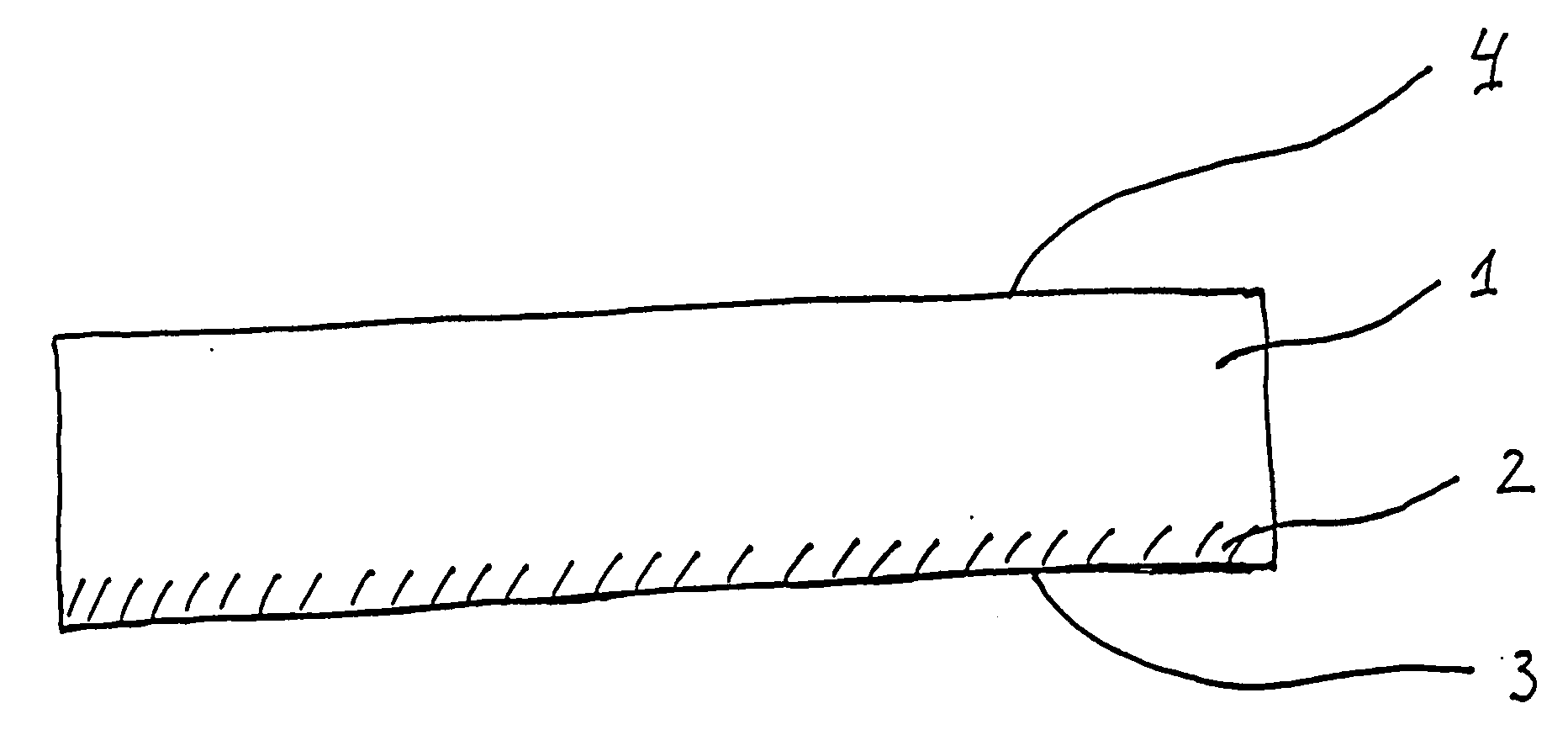
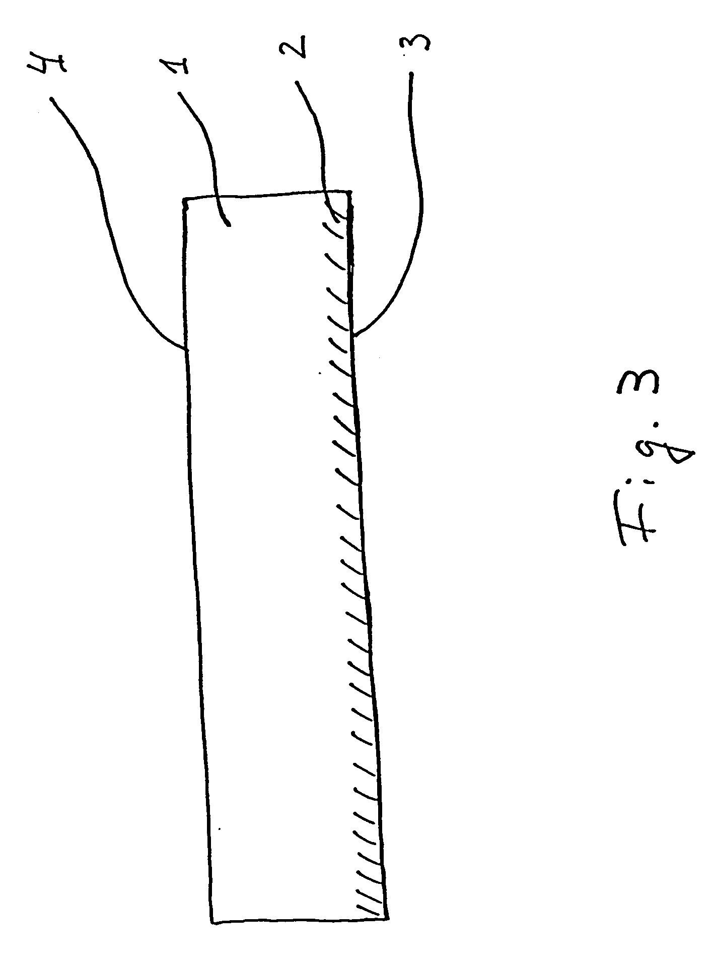
[0041]FIG. 3 depicts an inventive solid body, which in this embodiment has a first domain 1 and a second domain 2, and which in this embodiment form a mono-crystalline structure. The first domain 1 forms in this embodiment a passive domain and consists of potassium-yttrium-tungstenate, while the second domain 2 forms a laser active domain and consists of potassium-ytterbium-tungstenate.
[0042] The solid body has reflector layers on its upper side 4 and its lower side 3 whose purpose is to form a laser resonator.
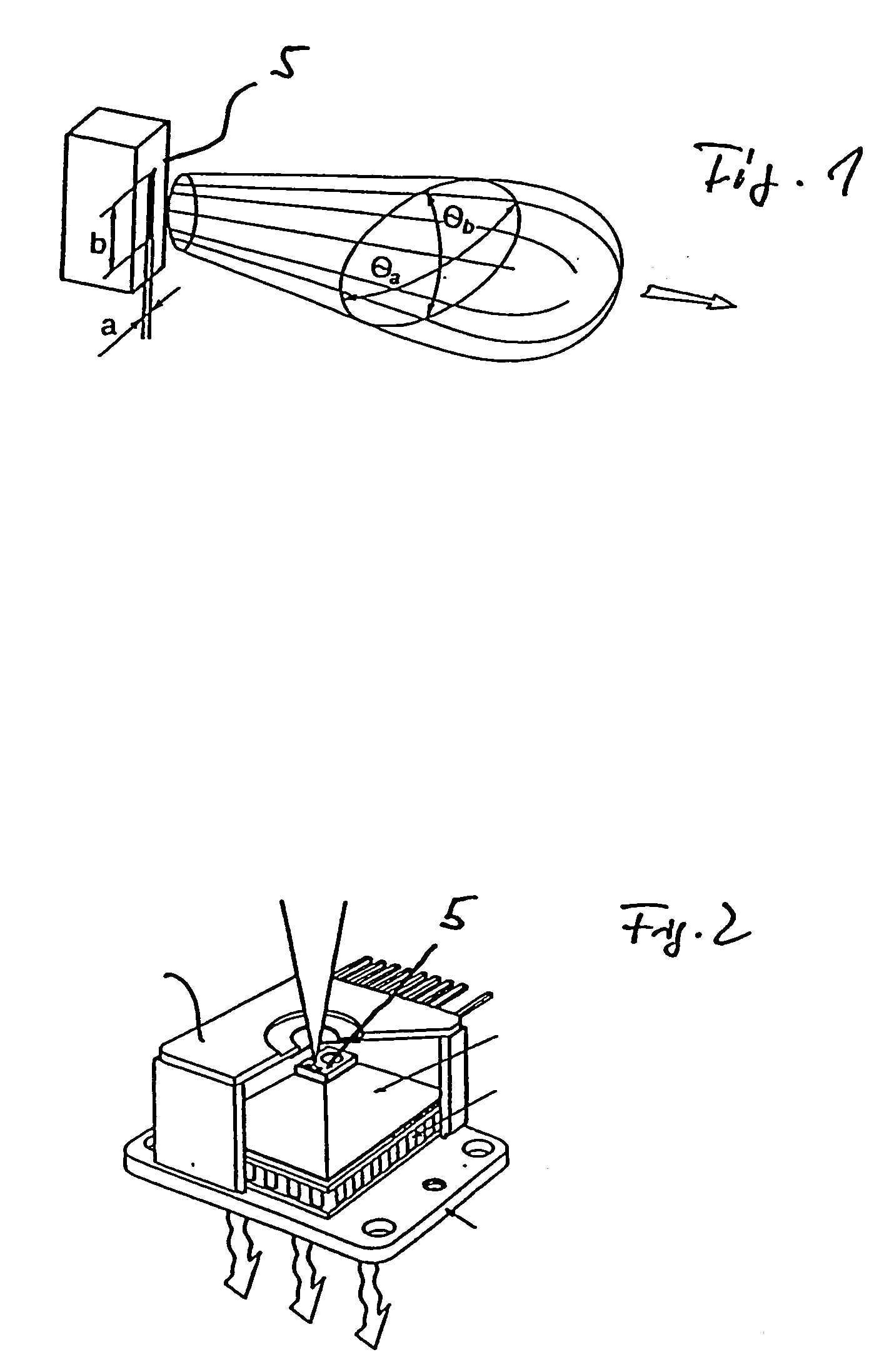
[0043] The inventive solid body can be pumped with a conventional laser diode 5 without additional adaptive optics and used as a laser. As depicted in FIG. 1 the beam of the laser diode 5, which serves to pump the laser active domain 2, is divergent and the cross section of the beam is elliptically shaped. However, the beam characteristic of the near field region is different from that of the far field region, whereby divergence angles of approximately 30° are common. Because...
second embodiment
[0047]FIG. 4 depicts an inventive solid body in the form of a laser that has a first passive domain 1 and a second active, here laser active, domain 2 that is connected to a mount 6. The laser active domain of this embodiment is about 50 μm thick, whereby a laser diode (not shown) is used for pumping. In this embodiment the laser active domain 2 is doped with ytterbium and additionally with up to 10 % Thulium (Tm). Owing to this combined doping with Ytterbium (Yb) and Thulium (Tm), excitation with a wavelength of 900 to 1000 nm is possible, whereby the laser beam has a wavelength of 2 μm.
third embodiment
[0048]FIG. 5 depicts an inventive solid body which has a first domain 10 having a thickness of about 40 μm and is made of KYbW, which is doped with 1 at-% Nd. Domain 10 is located between the two domains 12 and 14, which are made of potassium-yttrium-tungstenate (KYW). Because the refractive index of KYW is smaller than the refractive index of KYbW, domain 10 forms a wave guide. The solid body depicted in FIG. 5 can, for example, be used in conjunction with a chip laser, which emits at 1.4 μm.
[0049] One of the two domains 12 and 14 is formed particularly thin in order to reduce the thermal resistance. Absorption of the pump beam is transmitted quasi-resonantly to the Nd. The resonator reflectors are conductive at 1.06 μm and are at the second laser junction highly reflective at 1.35 μm.
[0050]FIG. 6 depicts an additional embodiment of an inventive solid body, which in this embodiment forms a high-performance disk laser. The solid body of this embodiment has a laser active first doma...
PUM
 Abstract
Description
Claims
Application Information