

Gas metal arc welding methods and apparatus
a metal arc welding and gas technology, applied in the direction of welding/cutting media/materials, welding apparatus, manufacturing tools, etc., can solve the problems of limited equipment limitations, achieve high productivity, reduce welding fumes, and improve welding quality
- Summary
- Abstract
- Description
- Claims
- Application Information
AI Technical Summary
Benefits of technology
Problems solved by technology
Method used
Image

Examples
example 1
Calculation of Spray Transfer Conditions in CO2 with a Mild Steel Electrode
[0055] The transition to spray transfer was assumed to correspond to the anode spot just enveloping the drop (the area of the anode spot being equal to the area of the drop minus the cross-sectional area of the wire) as suggested by Rhee and Kannatey-Asibu (Rhee, 1991). The anode current density for CO2 was assumed to be 3.3×10⁸ A / m2 as suggested by Haidar (Haidar 1998). A model based on that of Mendez et al. (Mendez, P. F., N. T. Jenkins, and T. W. Eagar. Effect of Electrode Droplet Size on Evaporation and Fume Generation in GMAW. in Gas Metal Arc Welding for the 21st Century. 2000. Orlando, Fla.: American Welding Society, pp. 325-332, Dec. 6-8, 2000), hereby incorporated by reference, was used to calculate the welding current based on the following processing inputs and material inputs:
Processing inputs:Electrode feed rateElectrode extensionWire diameterMaterial inputs:Solid:heat diffusivitydensityspecif...
example 2
GMAW Using Three Different Diameter Steel Wire Electrodes in Atmospheres Ranging from 0-40% CO2
[0058] Three different wires were compared in varying atmospheres of CO2 to investigate changes in transition current from globular to spray; FIG. 3 shows the results. The transition current was determined by Fast Fourier Transform analysis of the current signal. The balance of the shielding gas atmosphere was argon.
[0059]FIG. 3 shows that a transition from globular to spray metal transfer was observed for the 0.58 mm wire at both 30 and 40% carbon dioxide atmospheres. The wire feed rates for these conditions were between 800 and 1400 inches per minute.
Further experimental conditions were as follows:Electrode composition:ER70S-6Base plate composition:A36 structural steelVoltage range:15-50 VoltsCurrent range:15-400 AmperesElectrode Stickout:0.25 inchesTorch Angle:90° to the base plateTravel Speed:6-12 inches per minuteContact tip:Standard
[0060] The wire feeder was a commercially availa...
example 3
Contact Tip Assembly with Flexible Conducting Fingers
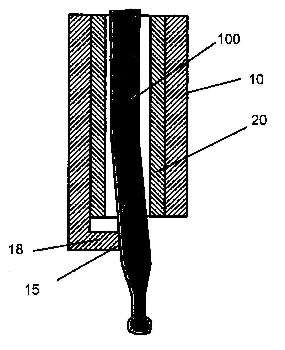
[0061]FIGS. 4A-4D illustrate a contact tip assembly suitable for use with the invention. FIG. 4A is a longitudinal cross-section of the contact tip assembly before insertion of the electrode wire (filler wire). FIG. 4B is a cross-section of the contact tip assembly in FIG. 4A along the dashed line in FIG. 4A. FIG. 4C is a longitudinal cross-section of the contact tip assembly after insertion of the wire. FIG. 4D is a cross-section of the contact tip assembly in FIG. 4C along the dashed line in FIG. 4C.
[0062] The contact tip assembly comprises an electrically conducting body 10 whose downstream end is formed into flexible conducting fingers 12. The conducting fingers are the sections of the conducting body between longitudinal slits 14 in the downstream end of the conducting body. FIG. 4B shows two conducting fingers being formed, although a greater number of fingers could be formed by additional slits in the conducting body. Ele...
PUM
| Property | Measurement | Unit |
|---|---|---|
| Fraction | aaaaa | aaaaa |
| Fraction | aaaaa | aaaaa |
| Diameter | aaaaa | aaaaa |
Abstract
Description
Claims
Application Information