Thermal barrier coating material

a thermal barrier and coating material technology, applied in the field of high temperature thermal barrier coating material and thermal barrier, can solve the problems of mismatching of internal stress and coating, short cycling life of the coated layer, and increased high temperatur

Inactive Publication Date: 2006-11-02
CHANGCHUN INST OF APPLIED CHEMISTRY - CHINESE ACAD OF SCI
View PDF3 Cites 32 Cited by
  • Summary
  • Abstract
  • Description
  • Claims
  • Application Information

AI Technical Summary

Benefits of technology

[0014] According to a further aspect, the invention provides a process for preparing a thermal barrier coating suitable to be used at a temperature higher than 1150° C., comprising a step of depositing a thermal barrier coating material having a fluorite structure and the chemical composition of (1−

Problems solved by technology

The occurrence of internal stress in the coating due to mismatch of thermal expansion at hi

Method used


Image

  • Thermal barrier coating material
  • Thermal barrier coating material

Examples


example 1

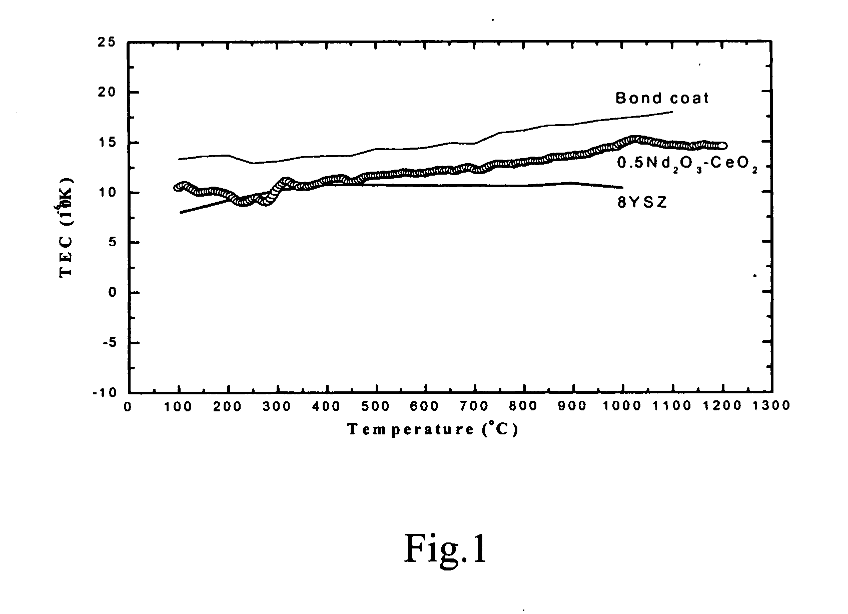
[0026] CeO2 powder and Nd2O3 powder were mixed in a molar ratio of 1:0.5. The mixture was ball milled for 1 hr and heated at 1600° C. for 2 hrs to give a powder sample of CeO2-0.5Nd2O3. The powder sample was subjected to spray drying treatment to yield a highly flowable powder. A NiCrAlY metal bond coating of thickness of about 100 μm was first deposited on the surface of nickel based superalloy by means of electron beam physical vapor deposition and then a CeO2-0.5Nd2O3 ceramic top coating of thickness of about 200 μm was deposited on the surface of the metal bond coating by means of the plasma spray.

example 2

[0027] Powders of CeO2, ZrO2 and Nd2O3 were mixed in a molar ratio of 0.1:0.9:0.5. The mixture was ball milled for 24 hrs and heated at 1400° C. for 12 hrs. The ball milling and heating were repeated 2 times under the same conditions to give a powder sample of 0.1CeO2-0.9ZrO2-0.5Nd2O3. The sample was subjected to spray drying treatment to yield a highly flowable powder. A Coral metal bond coating of thickness of about 150 μm was first deposited on the surface of nickel based superalloy by means of vacuum plasma spray coating and then on the surface of the metal bond coating a 0.1CeO2-0.9ZrO2-0.5Nd2O3 ceramic top coating of thickness of about 300 μm was deposited by means of plasma spray.

example 3

[0028] Powders of CeO2, ZrO2 and Nd2O3 were mixed in a molar ratio of 1:1:1. The mixture was ball milled for 72 hrs and heated at 1200° C. for 24 hrs. The ball milling and heating were repeated 3 times under the same conditions to give a powder sample of CeO2—ZrO2—Nd2O3. The sample was subjected to spray drying treatment to yield a highly flowable powder. On the surface of cobalt based superalloy a FeCrAlY metal bond coating of thickness of about 200 μm was first deposited by means of the vacuum plasma spray and then on the surface of the metal bond coating a CeO2—ZrO2—Nd2O3 ceramic top coating of thickness of about 600 μm was deposited by means of the electron beam physical vapor deposition.


PUM

PropertyMeasurementUnit
Temperatureaaaaaaaaaa

Abstract

The present invention relates to a thermal barrier coating material having the chemical composition of (1−n)CeO2-nZrO2-0.5R2O3, where n is in the range of 0.9≧n≧0 and R is selected from a group consisting of Nd, Sm, Eu, Gd, Tb and combinations of at least two among them. It possesses a thermal expansion coefficient higher than 12×10−6 K−1 from ambient temperature up to 1200° C. and superior to those of the presently widely-used thermal barrier coating materials. Even if it is subjected to long time calcinations at 1400° C. or is quenched to room temperature, it can still maintain the stable crystal structure. In addition, its thermal expansion trend matches quite well with that of the bond coating alloy. This is beneficial to the elimination of thermal stress generated between the substrate and the ceramic top coating during the thermal cycle and can significantly improve the thermal shock resistance of the coating. The present invention further relates to a method for producing a thermal barrier coating material and a method for preparing a thermal barrier coating.

Description

CROSS-REFERENCE TO RELATED APPLICATIONS [0001] This application claims the benefit of Chinese Patent Application No.: 2004100110900, filed Sep. 10, 2004. FIELD OF THE INVENTION [0002] The present invention relates to a high temperature thermal barrier coating material and a thermal barrier coating produced thereby. BACKGROUND OF THE INVENTION [0003] Along with the developments of civilian technologies of aviation, spaceflight, thermal power and etc, the demand on higher service temperature of the hot end parts of gas turbine engine is increasing. The superalloys and their single crystals are currently used at service temperatures approaching their upper limits of thermal stability. Under such a condition, from the viewpoint of improving material, the thermal barrier coating technique has been widely used as another feasible technique of reducing the surface working temperature of the vanes of the turbine engine. [0004] The comparison research of National Aeronautics and Space Admini...

Claims


Application Information

Patent Timeline
IPC IPC(8): C04B35/48C04B35/50B05D7/14C01F17/241C01G25/00C09D1/00C23C4/10C23C14/08C23C30/00
CPCC01F17/0043C23C30/00C01P2002/72C01P2006/20C04B35/48C04B35/50C04B35/62655C04B2235/3224C04B2235/3229C04B2235/3244C04B2235/9607C09D1/00C23C4/105C23C14/08C01G25/006C23C4/11C01F17/241
Inventor DAI, HUILI, JIAYANCAO, XUEQIANGMENG, JIAN
Owner CHANGCHUN INST OF APPLIED CHEMISTRY - CHINESE ACAD OF SCI
Why Eureka
Try Eureka