Liquid crystal projector

a liquid crystal projector and projector technology, applied in projectors, television systems, instruments, etc., can solve the problems of deteriorating image quality, affecting the clearness of projected images, and affecting the effect of image quality, so as to prevent dust or the like from being attached, enhance the heat radiation of light modulating means, and improve the effect of heat conductivity

Inactive Publication Date: 2006-11-23
SEIKO EPSON CORP
View PDF4 Cites 10 Cited by
  • Summary
  • Abstract
  • Description
  • Claims
  • Application Information

AI Technical Summary

Benefits of technology

[0008] An advantage of the invention is to provide a liquid crystal projector capable of enhancing heat radiation of light modulating means including a liquid crystal light valve and preventing dust or the like from being attached to the surface of the liquid crystal light valve. Another advantage of the invention is to provide a liquid crystal projector in which black matrixes formed between pixels in the liquid crystal light valve is made to be little visible.
[0009] According to an aspect of the invention, a liquid crystal projector comprises: a light source unit; colored-ray dividing means for dividing light emitted from the light source unit into three colored rays; light modulating means including a liquid crystal light valve and serving to modulate the three colored rays on the basis of a given image signal and to emit the modulated rays which are predetermined linear polarized rays; colored-ray synthesizing means for synthesizing the modulated rays; and optical projection means for enlarging and projecting the synthesized ray synthesized by the colored-ray synthesizing means onto a screen. Here, a first dust-proof glass, which is made of crystallized quartz or sapphire having a uniaxial crystal structure and serves to prevent dust from being attached to the light modulating means, is disposed on an entrance side of the liquid crystal light valve of the light modulating means and a second dust-proof glass, which is made of crystallized quartz or sapphire having birefringence and serves to prevent dust from being attached to the light modulating means, is disposed on an exit side thereof.
[0010] According to this configuration, since the first dust-proof glass and the second dust-proof glass made of crystallized quartz or sapphire having relatively high heat conductivity are disposed on the entrance and the exit of the light modulating means, the heat resulting from absorption of the light not passing through the light modulating means can be conducted to the dust-proof glasses, thereby efficiently radiating the heat. Accordingly, the characteristic of the light modulating means can be maintained, thereby obtaining a projected image with no brightness blur. It is also possible to prevent dust or the like from being attached to the surface of the light modulating means. In addition, since the second dust-proof glass disposed on the exit of the light modulating means is made of crystallized quartz or sapphire having birefringence, the black matrix is made to be invisible at the time of the synthesized ray onto the screen, by dividing the modulated ray output from the light modulating means into a normal ray and an abnormal ray and projecting the synthesized ray including the divided abnormal ray onto the black matrix, thereby improving the image quality.
[0011] A ¼ wavelength plate and a birefringent plate having birefringence may be disposed in an optical path between the second dust-proof glass having birefringence and the optical projection means, sequentially from an exit surface of the second dust-proof glass.
[0012] According to this configuration, since the ¼ wavelength plate and the birefringent plate having birefringence are disposed sequentially from the exit side of the second dust-proof glass having birefringence, the modulated rays divided into the normal rays and the abnormal rays by the second dust-proof glass are divided again into normal rays and abnormal rays by the birefringent plate and the synthesized rays synthesized by the colored-ray synthesizing means are enlarged and projected onto the screen. The synthesized rays divided into the normal ray and the abnormal ray are projected onto positions spaced apart from each other by a predetermined distance set in the horizontal and vertical directions, at the time of enlargement and projection of the rays onto the screen. The abnormal rays divided in the horizontal direction and the abnormal rays divided in the vertical direction two-dimensionally overlap with the black matrix of the image projected with the normal rays, thereby making the black matrixes further invisible. As a result, the quality of the image enlarged and projected onto the projection plane of the screen is improved.
[0013] The light modulating means, the first dust-proof glass, and the second dust-proof glass may be retained in a rectangular tube-shaped support member. According to this configuration, since the light modulating means, the first dust-proof glass, and the second dust-proof glass are retained in the rectangular tube-shaped support member, the heat generated from the light modulating means can be radiated to the rectangular tube-shaped support member through the first dust-proof glass and the second dust-proof glass, thereby enhancing a heat radiation effect of the light modulating means. As a result, the characteristic of the light modulating means can be maintained and thus a projected image with no brightness blur can be obtained.

Problems solved by technology

The heat has a bad influence on the characteristic of the polarizing plate or the liquid crystal panel, thereby deteriorating clearness of an image projected onto the screen.
When particles such as dust or damages exist on the surface of the liquid crystal panel, a defect occurs in the projected image.
The liquid crystal light valve used in the liquid crystal projector has the following problems, in addition to the generation of heat due to light emitted from a light source lamp and the attachment of dust.
When the number of pixels is small and the width of the black matrix is relatively large, or when the enlargement magnification is large, the black matrix is projected onto the image, thereby deteriorating image quality.
In addition, since the liquid crystal light valve tends to decrease in size, the aperture ratio (ratio between an area of the opened part transmitting light and an area of the black matrix) is decreased, thereby deteriorating the image quality.

Method used


Image

  • Liquid crystal projector
  • Liquid crystal projector
  • Liquid crystal projector

Examples


first embodiment

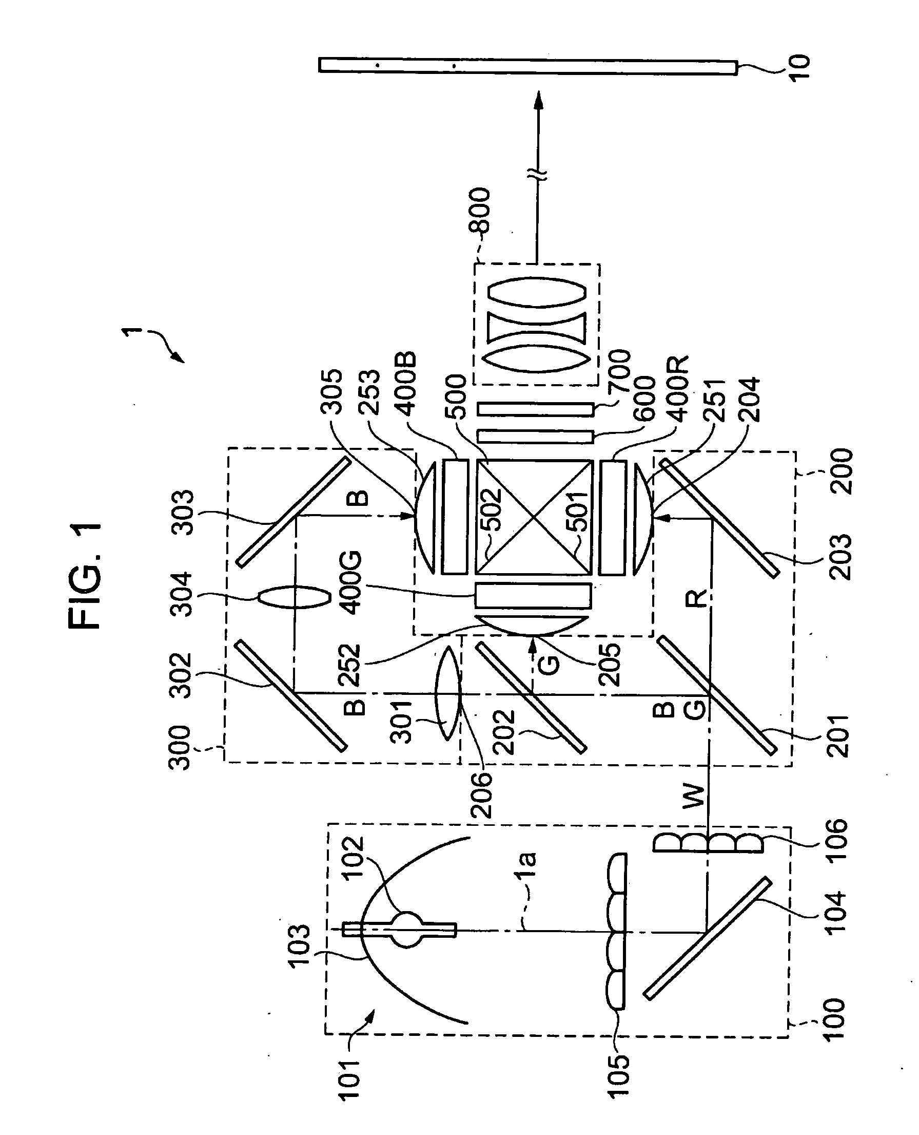
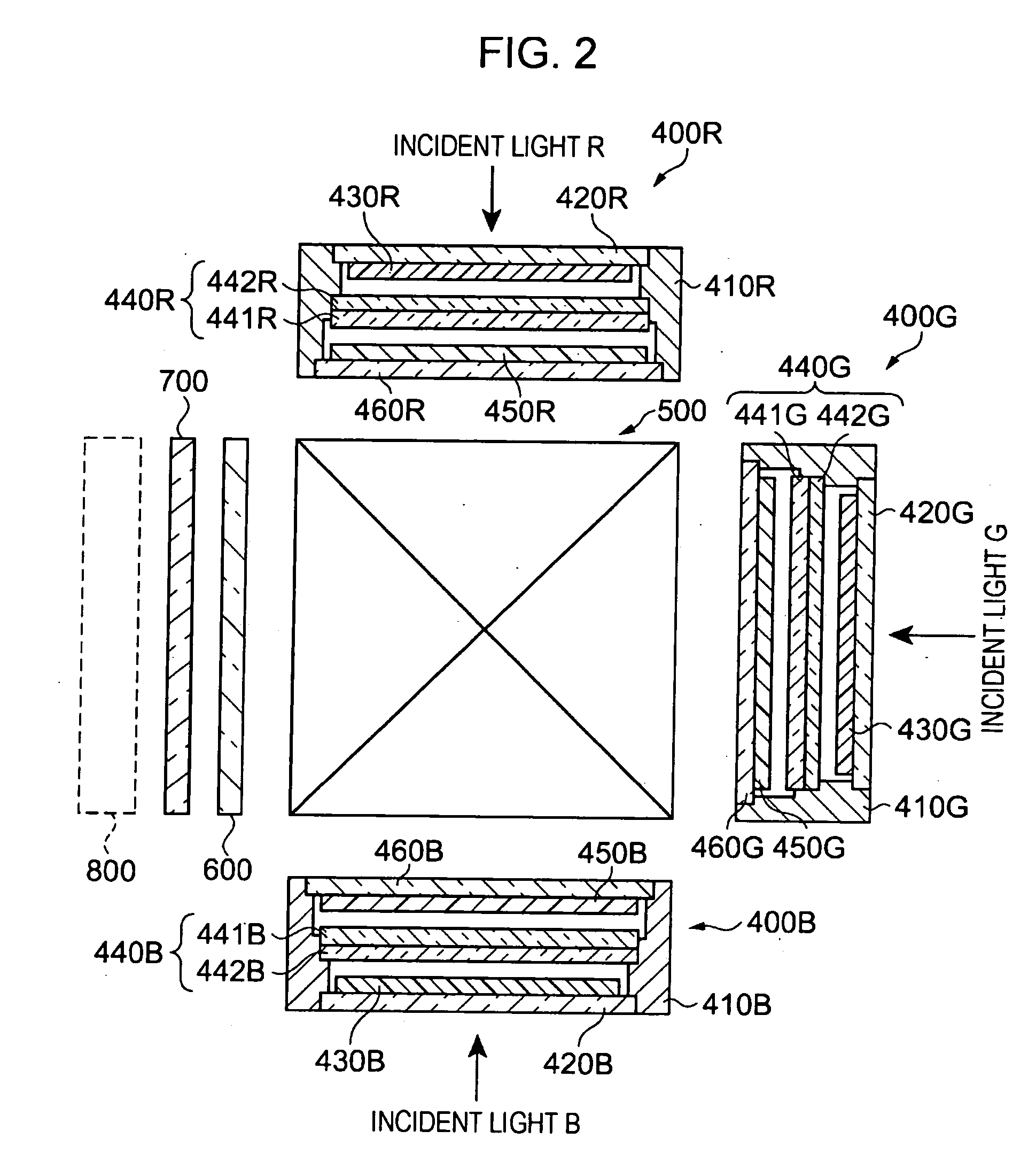
[0032]FIG. 1 is a plan view schematically illustrating a liquid crystal projector according to a first embodiment of the invention and FIG. 2 is a partial plan view illustrating an optical system.

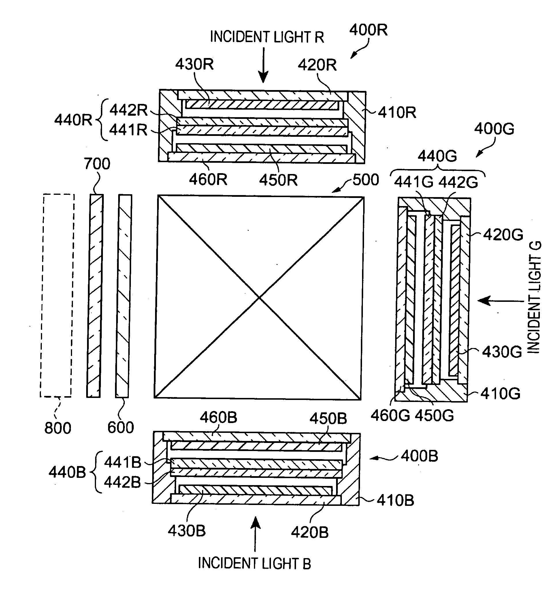
[0033] Referring to FIG. 1, the liquid crystal projector 1 includes a lighting optical system 100, a colored-ray dividing optical system 200 as colored-ray dividing means, liquid crystal units 400R, 400G, and 400B, dichroic prism 500 (hereinafter, referred to as prism) as colored-ray synthesizing optical means, a ¼ wavelength plate 600, a birefringent plate 700 as a second birefringent plate, and a projection lens 800 as optical projection means. The liquid crystal projector 1 further includes a relay lens system 300 for guiding blue rays B among colored rays divided by the colored-ray dividing optical system 200 to the liquid crystal unit 400B.

[0034] The lighting optical system 100 includes a reflecting mirror 104 for bending an optical axis 1a of light emitted from the light source unit...

second embodiment

[0078] A second embodiment of the invention provides a liquid crystal projector in which the ⅓ wavelength plate 600 and the birefringent plate 700 as the second birefringent plate disposed between the dichroic prism 500 and the projection lens 800 in the first embodiment are disposed inside the liquid crystal unit. Accordingly, the configuration and function other than the liquid crystal unit 400 are similar to those of the first embodiment and thus description thereof will be omitted.

[0079]FIG. 5 is a partial plan view illustrating an optical system according to the second embodiment of the invention. The same elements as the first embodiment are denoted by the same reference numerals.

[0080] Liquid crystal units 900R, 900G, and 900B have the same structure. Colored rays are incident on the liquid crystal units 900R, 900G, and 900B through the light condensing lenses 251, 252, and 253 from the colored-ray dividing optical system 200 and the relay lens system 300. Each liquid cryst...

third embodiment

[0096]FIG. 6 is a partial plan view illustrating an optical system according to a third embodiment of the invention.

[0097] The third embodiment of the invention provides a liquid crystal projector having a structure that the ¼ wavelength plate 600 and the birefringent plate 700 as the second birefringent plate in the first embodiment are omitted. Accordingly, the structure and the transmission state of the ray exiting from the prism 500 are similar to the first embodiment and thus description thereof will be omitted.

[0098] The first embodiment and the second embodiment provide the liquid crystal projector having a dividing function that the respective synthesized rays indicating the synthesized color image enlarged and projected onto the projection plane of the screen 100 through the projection lens 800 are divided into four points of a tetragonal shape in the horizontal and vertical directions, but the third embodiment provides a liquid crystal projector having a dividing functio...


PUM

PropertyMeasurementUnit
transmittanceaaaaaaaaaa
angleaaaaaaaaaa
tilting angleaaaaaaaaaa

Abstract

There is provided a liquid crystal projector capable of enhancing heat radiation of light modulating means including a liquid crystal light valve, preventing dust or the like from being attached to the surface of the liquid crystal light valve, and making black matrixes formed between pixels in the liquid crystal light valve invisible. The liquid crystal projector includes a light source unit, colored-ray dividing means for dividing light emitted from the light source unit into three colored rays, light modulating means for serving to modulate the three colored rays on the basis of a given image signal and to emit the modulated rays which are predetermined linear polarized rays, colored-ray synthesizing means for synthesizing the modulated rays, and optical projection means for enlarging and projecting the synthesized rays synthesized by the colored-ray synthesizing means onto a screen. The light modulating means includes entrance dust-proof glasses 420R, 420G, and 420B made of crystallized quartz or sapphire having a uniaxial crystal structure and disposed on entrance sides of liquid crystal light valves 440R, 440G, and 440B of the light modulating means, respectively, and exit dust-proof glasses 460R, 460G, and 460B made of crystallized quartz or sapphire having birefringence and disposed on exit sides thereof, respectively.

Description

BACKGROUND [0001] 1. Technical Field [0002] The present invention relates to a liquid crystal projector displaying an image of a liquid crystal display by projection. [0003] 2. Related Art [0004] Liquid crystal projectors have been widely known as image projecting apparatuses used for presentation or home theater. The liquid crystal projector includes liquid crystal light valves (liquid crystal panels) as light modulating means and a light source lamp for irradiating light to the liquid crystal light valves and displays an image by projecting light modulated by the liquid crystal panels onto a screen. In order to cope with decrease in size, increase in precision, and increase in brightness in the liquid crystal projector, a light source lamp for irradiating more intensive light is used. [0005] The liquid crystal light valve used in the liquid crystal projector includes a polarizing plate on a light entrance surface and a light exit surface. The polarizing plate has a function of tra...

Claims


Application Information

Patent Timeline
Patent Type & Authority Applications(United States)
IPC IPC(8): G02F1/1335
CPCG03B21/00G03B21/006H04N5/74
Inventor UEHARA, TAKEHIKOHARA, KAZUHIROMUKAIYAMA, HIROYUKI
Owner SEIKO EPSON CORP
Why Eureka
Try Eureka