Porous structures and methods for forming porous structures

a porous structure and porous technology, applied in the field of porous structures and methods for forming porous structures, can solve the problems of many polymer-based filter media degrading from the heat of such hot fluid streams, contaminants in process fluids can deposit onto semiconductor or semiconductor precursors, damage, etc., to achieve the effect of reducing pressure differential, increasing ductility, and increasing ductility

Inactive Publication Date: 2006-12-07
PALL CORP
View PDF3 Cites 28 Cited by
  • Summary
  • Abstract
  • Description
  • Claims
  • Application Information

AI Technical Summary

Benefits of technology

[0009] Porous inorganic filter media derived from inorganic particles having at least two different nominal sizes can provide for a number of advantages. For example, a porous inorganic filter medium made from inorganic particles having at least two different nominal sizes can have increased ductility and/or exhibit a reduced pressure differential. A porous inorganic filter medium with increased ductility is less likely to break or crack when subjected to pressure. Moreover, porous inorganic filter media made from particles having at least two different nominal sizes can result in a porous inorganic filter medium having an increased surface area and thus improved particulate retention properties. For example, if an inorganic filter medium is made from a plurality of inorganic particles having a small size and a plurality of inorganic particles having a larger size, the larger size inorganic particles can define large pores in the filter medium. The smaller size particles, which can

Problems solved by technology

On the other hand, many polymer-based filter media will degrade from the heat of such hot fluid streams.
In contrast, many polymeric filters cannot be sterilized for reuse, because most polymers are not suitable for high temperature sterilization.
If these process fluids are not highly pure at the point of use, contaminants in the process fluids can deposit onto a semiconductor or semiconductor precursor and damage it (e.g., by causing a defective circuit).
Damaged semiconductors are typically reworked or discarded as scrap.
However, organic filter media can unfavorably exhibit particle shedding, organic desorption (e.g., outgassing or leaching of extractables), clogging, thermal degradation and chemical degradation.
However, conventional metallic filter media also have disadvantages including poor contaminant retention properties, low voids volumes, low ductility, and/or a high pressure drop.
Further, some conventional methods

Method used


Image

  • Porous structures and methods for forming porous structures
  • Porous structures and methods for forming porous structures
  • Porous structures and methods for forming porous structures

Examples


example 1

[0061] A slurry is formed by mixing 1 liter of methanol and 5 grams of 934 Carbopol binder in a blender. Into this slurry mixture in sequence is blended 1.79 grams of Triton X surfactant, 80 grams of Oximide 4μ spacer particles, 160 grams of Inco 255 nickel powder having a nominal particle size of about 2.7μ, and 107 grams of Inco 210 nickel powder having a nominal particle size of about 7μ. This slurry mixture is mixed in the blender until the slurry has a relatively uniform composition and the presence of pockets and / or clumps in the slurry is minimized, e.g., about 10-20 minutes. Once the slurry appears to be substantially uniform, the slurry is deposited in the cavity of a female mold on a 0.5 micron Teflon membrane which rests on a screen in the female mold. The area of the female mold is about 2 inches by 5 inches and the slurry is deposited to a depth of about 0.25 inch. Once deposited, a countermold is inserted into the cavity containing the slurry. The weight of the counter...

example 2

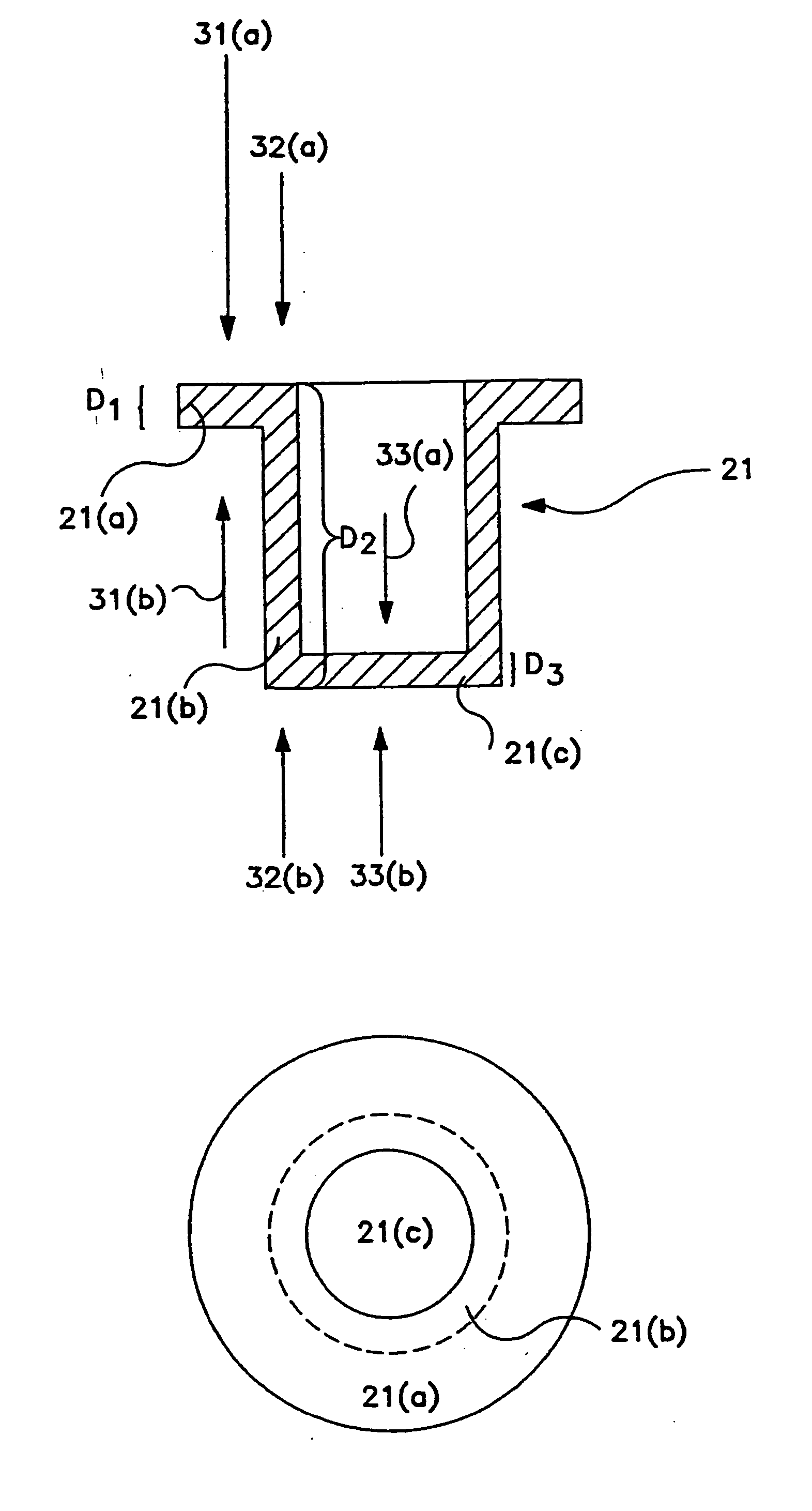
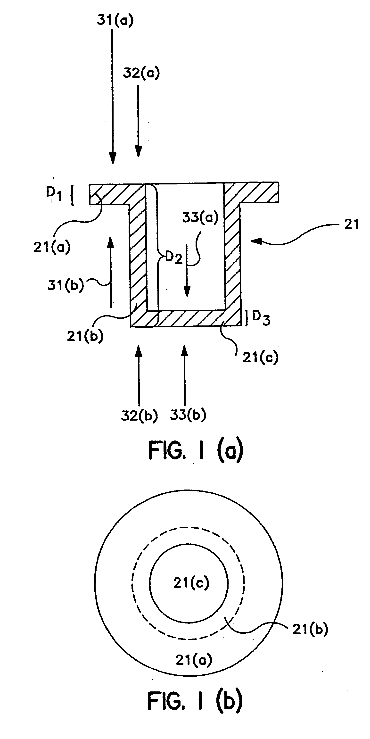
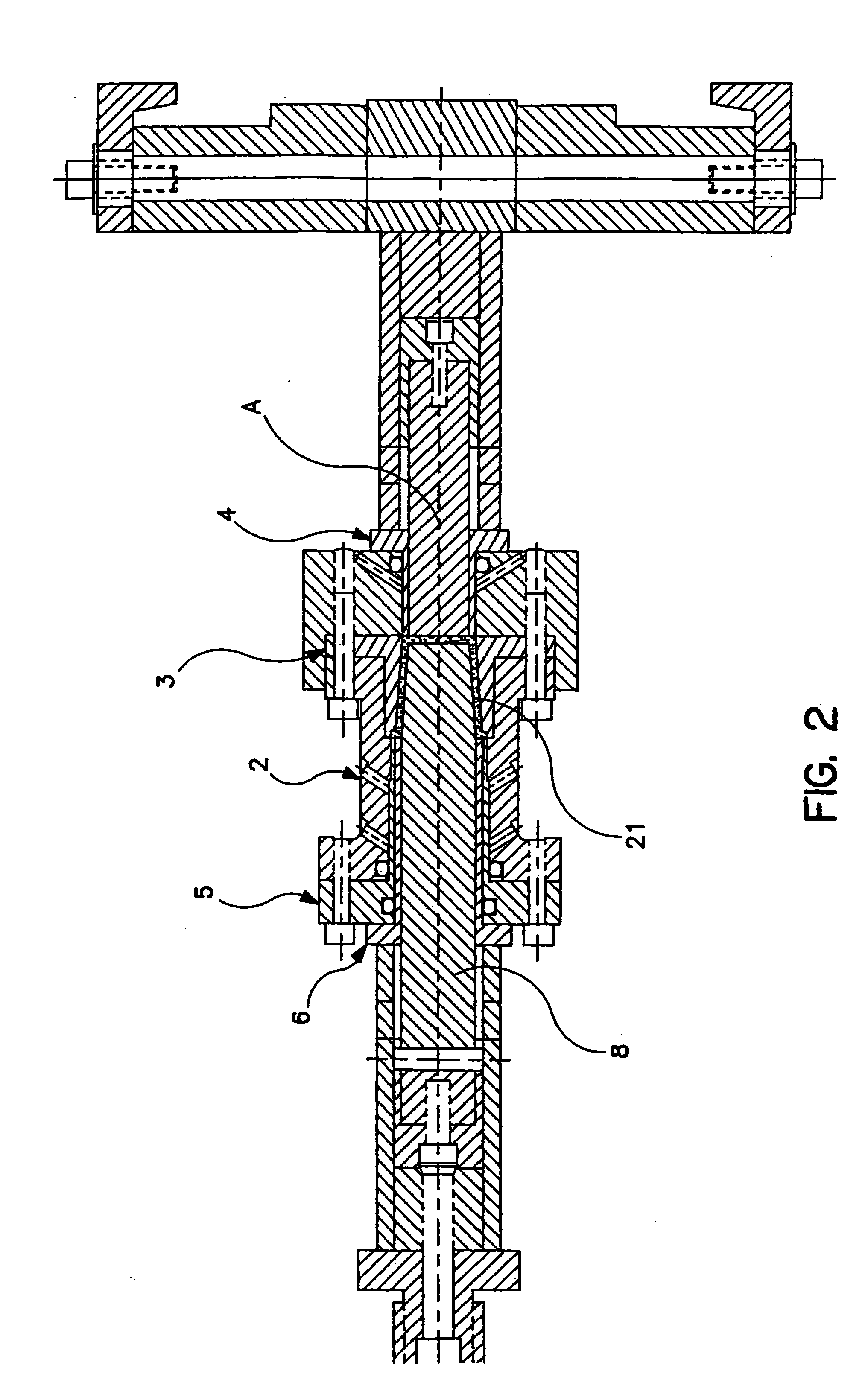
[0062] 16.3 grams of the slurry mixture of Example 1 is deposited in a mold apparatus of the type shown in FIG. 2. The dies are positioned against the slurry to define a first portion, e.g., a brim portion, a second portion, e.g., a sidewall or body portion, and a third portion, e.g., an end portion. The dies are then actuated such that the does move at a rate of about 1 inch per minute or less to provide a 55% compression ratio for each of the first, second, and third portions. The dies forming the first and third portions move through an axial displacement of about 0.080 inch to form first and third portions having a thickness of about 0.065 inch and the dies forming the second portion move through a total axial displacement of about 1.375 inches to form a second portion having an axial dimension of about 1.19 inches. This uniform compression ratio provides a uniform porosity for each of the three portions. As the pistons are moved along their axial displacement, liquid from the s...

example 3

[0063] A slurry is formed by mixing about 1 liter DI water and 15 grams of 934 Carbopol binder in a blender. Into this slurry mixture is blended 35 grams of 1.5 micron 3-6-L stainless steel fibers. This slurry mixture is mixed in the blender until the slurry has a relatively uniform composition and the presence of pockets and / or clumps in the slurry is minimized. Then 148 grams of the slurry mixture is deposited in the cavity of a female mold on a 0.5 micron teflon membrane which rests, in turn, on a fine screen which rests on a coarser screen in the female mold. The inner diameter of the female mold is about 1.375 inches. A piston presses the slurry until the green structure is a 0.070 inch thick disk, removing some or most of the ill water and forming a green structure. The green disk is removed from the mold and air dried at room temperature. The dried green structure is then sintered in a hydrogen atmosphere at about 1800° F. for about 30 minutes. Sintering the metallic particle...


PUM

PropertyMeasurementUnit
Fractionaaaaaaaaaa
Fractionaaaaaaaaaa
Fractionaaaaaaaaaa

Abstract

A porous element is produced from a slurry of inorganic particles including a first plurality of inorganic particles having a first nominal size and a second plurality of inorganic particles having a second nominal size. The first nominal size is less than the second nominal size. The inorganic particles are sinter bonded.

Description

[0001] This application is a divisional of U.S. application Ser. No. 09 / 763,597, filed on Jul. 2, 2001, which is a national phase application of PCT Application PCT / US99 / 19153, filed on Aug. 24, 1999, which claimed the benefit of provisional U.S. application Ser. No. 60 / 097,687, filed on Aug. 24, 1998, all of which are hereby incorporated by reference.BACKGROUND OF THE INVENTION [0002] Inorganic filters have a number of advantages over other types of filters, such as polymeric filters. Since inorganic materials such as metals are generally more heat and chemical resistant than organic materials such as polymers, inorganic filter media can be used in applications where polymeric filter media cannot be used. For example, a metal filter can be used to separate fine catalytic particles from a hot gaseous stream or separate contaminants from a hot stream of polymeric liquid. On the other hand, many polymer-based filter media will degrade from the heat of such hot fluid streams. In additi...

Claims


Application Information

Patent Timeline
IPC IPC(8): B01D24/00B01D39/20B22F3/00B22F3/02C04B38/00
CPCB01D39/2034B01D39/20
Inventor LOVE, CHARLESREKCZIS, KEITHHOPKINS, SCOTT
Owner PALL CORP
Why Eureka
Try Eureka