Fluorescence measurement apparatus

a fluorescence measurement and apparatus technology, applied in the direction of fluorescence/phosphorescence, luminescent dosimeters, optical radiation measurement, etc., can solve the problems of increasing the s/n ratio of measurement, increasing the sensitivity of detection, and prone to autofluorescence, so as to achieve high sensitivity, increase fluorescence, and high sensitivity

Active Publication Date: 2007-01-04
PHC HLDG CORP
View PDF10 Cites 13 Cited by
  • Summary
  • Abstract
  • Description
  • Claims
  • Application Information

AI Technical Summary

Benefits of technology

[0036] According to a fluorescence measurement apparatus of the present invention, a wavelength selection means is provided on an upper surface of a substrate holding a sample that emits fluorescence when being irradiated with excitation light, which wavelength selection means reflects the excitation light and transmits the fluorescence, and the fluorescence that has passed through the wavelength selection means is measured by a light receiving unit. Therefore, autofluorescence from the substrate due to the excitation light is not emitted, resulting in highly sensitive measurement of a small amount of fluorescent sample. Further, since the wavelength selection means reflects the excitation light and the reflected excitation light again irradiates the sample, the fluorescence can be increased.
[0037] Furthermore, according to the fluorescence measurement apparatus of the present invention, a top plate having, on its one surface, a reflection layer for reflecting the excitation light is disposed on a substrate, and a sample is held with the wavelength selection means and the reflection layer of the top plate. Therefore, fluorescence can be amplified by irradiating the sample with the excitation light plural times, whereby a small amount of fluorescent substance can be measured with higher sensitivity.

Problems solved by technology

Although, as described above, such high-polymer materials are easily moldable, they tend to emit autofluorescence when irradiated with excitation light.
The autofluorescence causes a background noise, thereby getting the S / N ratio of the measurement worse.
Also in this case, as described above, autofluorescence emitted from a substrate as a channel causes background noise during fluorescence measurement, thereby getting detection sensitivity worse.
Therefore, the autofluorescence signal is undesirably added over the fluorescence signal.
Especially when measuring a sample having a small fluorescence signal, a fluorescence signal is difficult to detect because of an autofluorescence signal, which makes it difficult to detect a small fluorescence of sample with high sensitivity.
Further, in the method of reducing autofluorescence from a substrate by covering a part of a substrate other than a fluorescence measurement part, which is proposed by Patent Document 3, autofluorescence undesirably occurs from a bottom of a sample holder.
Therefore, when measuring a sample emitting a small fluorescence signal, a fluorescence signal is difficult to detect because of an autofluorescence signal, which makes it difficult to perform highly sensitive detection.
Moreover, thin film fabrication processes for the light shielding film is complicated.
Especially when measuring a sample having a small fluorescence signal, the noise signal significantly deteriorates the S / N ratio.
Further, in the method for making a material itself of a substrate not to emit autofluorescence, which is proposed by Patent Documents 5 and 6, it is difficult to completely prevent the material from emitting autofluorescence, and therefore, a small amount of autofluorescence is emitted from the substrate.
Especially when measuring a sample having a small fluorescence signal, the autofluorescence significantly deteriorates the S / N ratio.
Further, in the method of irradiating excitation light onto a side surface of an electrophoresis gel cassette by fluorescence measurement in electrophoresis, when irradiating the excitation light onto the side surface of the electrophoresis gel cassette, it is difficult to irradiate the excitation light to the entire gel evenly, and moreover, a complicated optical control for irradiating the excitation light onto the side surface of the electrophoresis gel cassette is required.
Therefore, this method is not practical.
However, none of these methods has sufficient performance for detecting a small amount of sample signal.

Method used


Image

  • Fluorescence measurement apparatus
  • Fluorescence measurement apparatus
  • Fluorescence measurement apparatus

Examples


embodiment 1

[0048] Hereinafter, a fluorescence measurement apparatus according to a first embodiment of the present invention will be described with reference to the drawings.

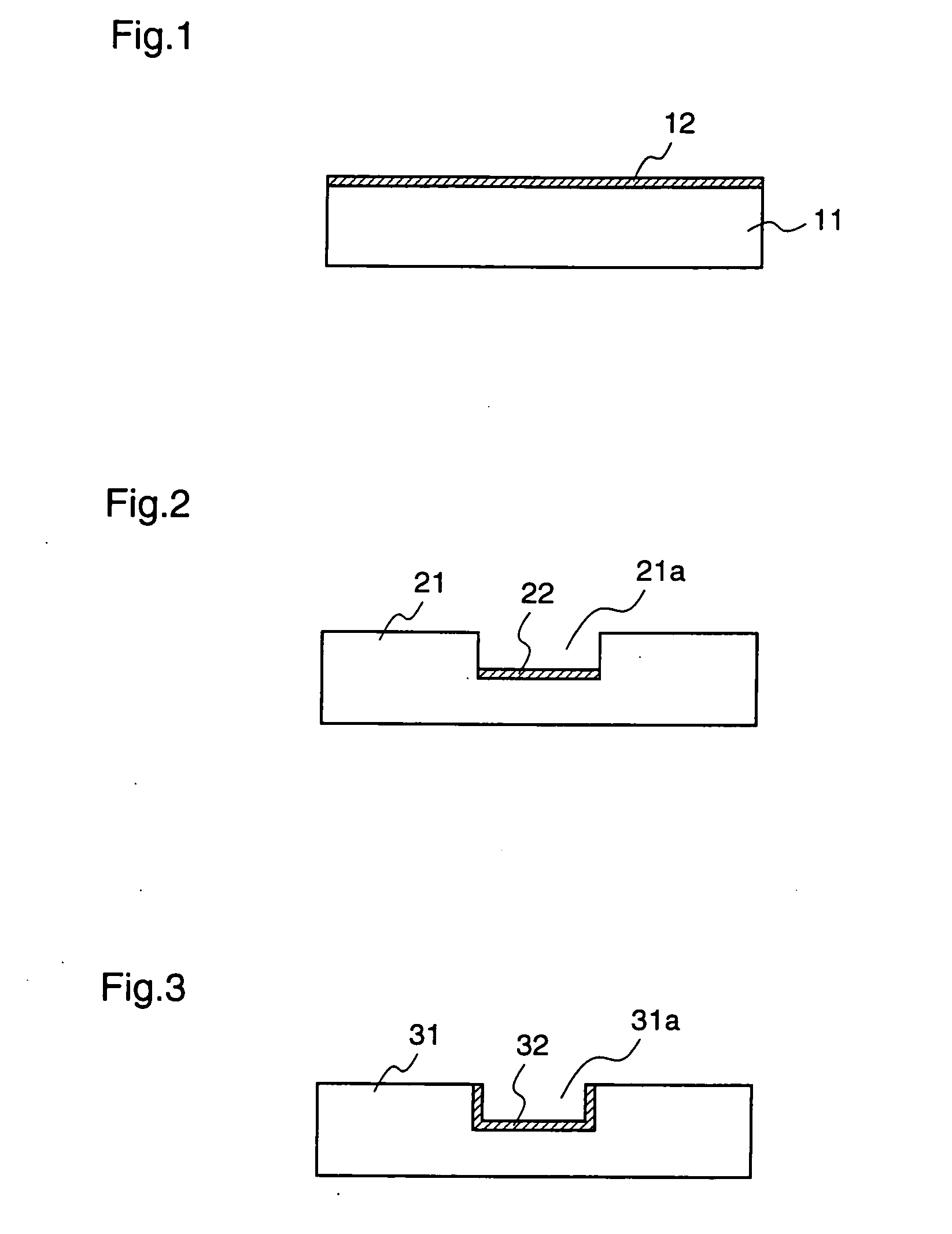
[0049] Initially, the construction of a substrate according to the first embodiment will be described with reference to FIGS. 1˜3. In this first embodiment, a “substrate” means any of a substrate, a cell, and a channel on which a sample is disposed.

[0050] FIGS. 1˜3 are end views illustrating examples of substrates according to the first embodiment. FIG. 1 shows a flat-plate-shaped substrate, and FIGS. 2 and 3 show substrates on which concave wells or channels are formed, respectively.

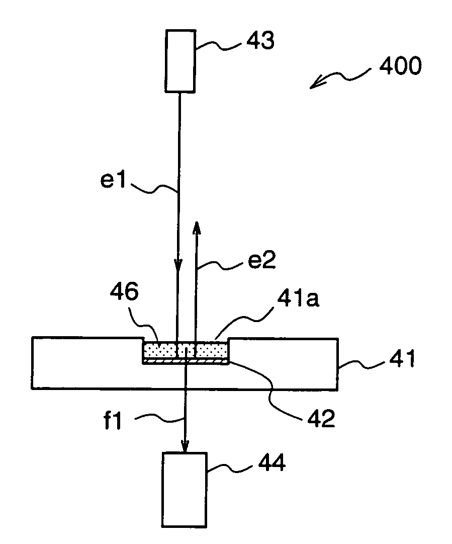
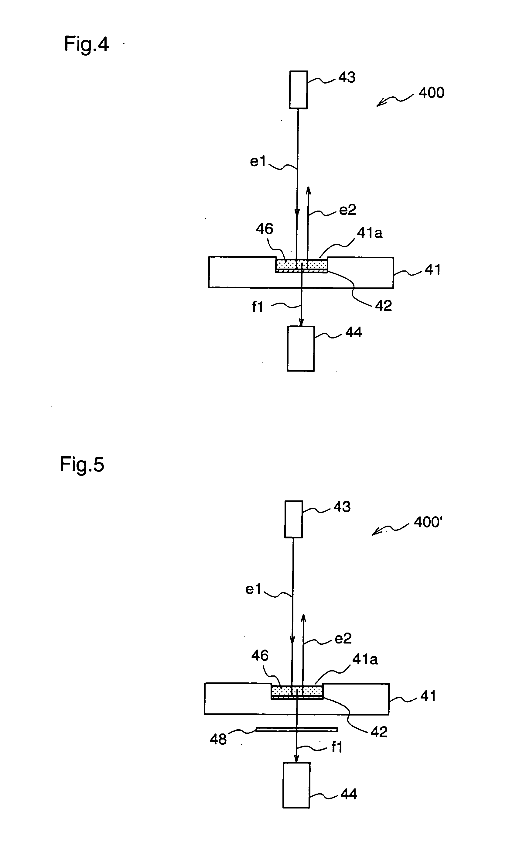
[0051] As shown in the figures, the substrates 11, 21, and 31 according to the first embodiment are provided with wavelength selection means 12, 22, and 32, respectively, for reflecting excitation light, and transmitting fluorescence that is emitted from samples disposed on the respective substrates. The wavelength selection means 12, 22, a...

example 1

[0076] Hereinafter, an example of a fluorescence measurement apparatus will be described with reference to FIG. 7. The fluorescence measurement apparatus of the present invention is not restricted to the construction described hereinafter.

(1) Fabrication of Substrate

[0077] A substrate 61 comprising a high-transparency polymethylmethacrylate, in which a concave channel 61a having a width of 80˜120 μm and a depth of 30˜70 μm is formed at the surface, is prepared, and a dielectric multilayer 62 is coated at the bottom surface of the channel 61a.

[0078] The dielectric multilayer 62 has a construction in which a high refractive index layer A (titanium dioxide, refractive index 2.4) and a low refractive index layer B (silicon dioxide, refractive index 1.5) are alternately deposited. Both the high refractive index layer A and the low refractive index layer B are deposited by reactive sputtering.

[0079] Hereinafter, film depositing conditions by reactive sputtering used in this example w...

example 2

[0085] Hereinafter, another example of a fluorescence measurement apparatus will be described with reference to FIG. 9. The fluorescence measurement apparatus of the present invention is not restricted to the construction described hereinafter.

(1) Fabrication of Substrate

[0086] A substrate 61 on which a dielectric multilayer 62 is deposited, which is used in this second example, is fabricated in the same method as that described for the first example.

(2) Placement of Top Plate

[0087] In this second example, a top plate 91 having, on its one surface, deposition of a reflection layer 92 that reflects the excitation light emitted from the excitation light source 63, is disposed on the concave channel 61a formed in the substrate 61 so that the reflection layer 92 faces the substrate 61. At this time, the top plate 91 is disposed on the substrate 61 so as not to entirely cover the opening of the channel 61a that is formed in the substrate 61, i.e., the top plate 91 is disposed so as...


PUM

PropertyMeasurementUnit
transmittanceaaaaaaaaaa
refractive indexaaaaaaaaaa
fluorescence wavelengthaaaaaaaaaa

Abstract

There is disposed, on a substrate 41 holding a sample to be detected, a dielectric multilayer 42 which reflects excitation light e1 supplied from above the substrate 41 and transmits fluorescence f1 emitted from the sample, and the excitation light e1 is reflected at the dielectric multilayer 42 while the transmitted fluorescence f1 is detected by a light receiving unit 44, thereby providing a fluorescence measurement apparatus which can resolve a problem of reduction in detection sensitivity due to autofluorescence from the substrate or leakage of the excitation light from a light receiving filter, and which can detect the sample with high sensitivity.

Description

FIELD OF THE INVENTION [0001] The present invention relates to a fluorescence measurement apparatus for measuring fluorescence emitted from a sample that is irradiated with excitation light, and more particularly, to a fluorescence measurement apparatus which reduces autofluorescence of a substrate that holds the sample. BACKGROUND OF THE INVENTION [0002] Conventionally, as a method for detecting biomolecules such as nucleic acid, protein, and enzyme, a fluorescence measurement method utilizing fluorescence reaction has been adopted. Since the fluorescence measurement method can perform measurement of biomolecules safely and inexpensively by combining existing optical components such as a light source and a light receiving unit without using a radioisotope, it is applied to various kinds of biomolecule detection methods such as enzyme immunoassay, electrophoresis, and confocal scanning fluorescence microscope. [0003] The fluorescence measurement is a method for detecting a fluoresce...

Claims


Application Information

Patent Timeline
Patent Type & Authority Applications(United States)
IPC IPC(8): G01N21/64G01N1/10
CPCG01N21/03G01N21/031G01N2021/0346G01N21/6452G01N2021/6471G01N21/645
Inventor TABATA, JIMPEIMIYAGAWA, SATOSHI
Owner PHC HLDG CORP
Why Eureka
Try Eureka