Method for improvement of performance of si thin film anode for lithium rechargeable battery

a lithium rechargeable battery and thin film anode technology, which is applied in the manufacture of electrodes, cell components, cable/conductor components, etc., can solve the problems of poor charge/discharge cycle characteristics, mechanical and electrical degradation, and capacity decline, so as to improve the charge/discharge cycle characteristics of lithium secondary batteries, improve the problem of electrical contact loss, and improve the effect of battery charge/discharge cycle characteristics

Active Publication Date: 2007-01-11
LG ENERGY SOLUTION LTD
View PDF6 Cites 50 Cited by
  • Summary
  • Abstract
  • Description
  • Claims
  • Application Information

AI Technical Summary

Benefits of technology

[0006] Therefore, the present invention has been made in view of the above problems, and it is an object of the present invention to provide a method for improving charge / discharge cycle characteristics of a lithium secondary battery using a Si based anode active material.
[0007] The present inventors have conducted a variety of extensive and intensive study and experimentation to solve the most important problem as described above, that is, loss of electrical contact between a silicon film and anode current collector when charging / discharging, exhibited by the lithium secondary battery including the Si based anode active material. As a result of such extensive investigation, the inventors have found that when the anode current collector is treated to have specific surface morphology, the problem of electrical contact loss can be greatly improved, and further found that it is possible to remarkably improve charge / discharge cycle characteristics of the battery by applying bias voltage to the current collector, in the course of vapor-depositing the silicon film on the surface-treated anode current collector by sputtering, and / or disposing an adhesive layer between the anode current collector and silicon film. The present invention has been completed based on these findings.
[0008] Therefore, in the lithium secondary battery using the Si based anode active material, the method for improving charge / discharge cycle characteristics of the battery in accordance with the present invention comprises surface-treating the anode current collector such that the surface morphology of the anode current collector has grain boundaries of 5 to 100 μm in size throughout the entire surface of the anode current collector, and trenches having a depth of more than 1 μm formed at grain boundary junctions.

Problems solved by technology

However, Si undergoes significant changes in volume thereof over continuous charge / discharge cycles, which causes mechanical and electrical degradation, and thus such poor charge / discharge cycle characteristics have been raised as the point at issue.
The reason of capacity decrease occurring in the course of the charge / discharge cycle is generally known to be due to loss of electrical contact between the silicon film and current collector.

Method used


Image

  • Method for improvement of performance of si thin film anode for lithium rechargeable battery
  • Method for improvement of performance of si thin film anode for lithium rechargeable battery
  • Method for improvement of performance of si thin film anode for lithium rechargeable battery

Examples


example 1

[0051] FeCl3 was mixed to a final concentration of 0.4 M in an aqueous 2.4 M HCl solution to prepare an etching solution that was then used in surface treatment by etching the surface of a Ni foil for about 1 min. On the surface treated-Ni foil current collector, a Si thin film of 5000 Å thickness was formed from a Si target having a diameter of 2″ (99.99%) by R.F. magnetron sputtering. Sputtering was performed in a chamber which had been vacuum pumped to 2×10⁻⁶ Torr and then set to 5 mTorr by injection of argon gas.

[0052] In order to confirm electrochemical properties of the Si thin film electrode, two #2016 coin cell batteries were prepared using a pure Li foil as a cathode, and a mixed solution in which 1M LiPF6 was added to a mixed solvent of ethylene carbonate (EC) and diethylene carbonate (DEC) (volume ratio 1:1), as an electrolyte solution. These cell batteries were assembled in a globe box under argon atmosphere, and were then subjected to more than 30 charge / discharge expe...

example 2

[0053] In order to confirm effects due to application of bias voltage during sputtering, the following experiments were performed: Experiment A; vapor-deposition of a Si thin film on a Si-wafer by sputtering, and Experiment B; vapor-deposition of the Si thin film on the Si-wafer by sputtering while applying DC bias voltage of −100 V.

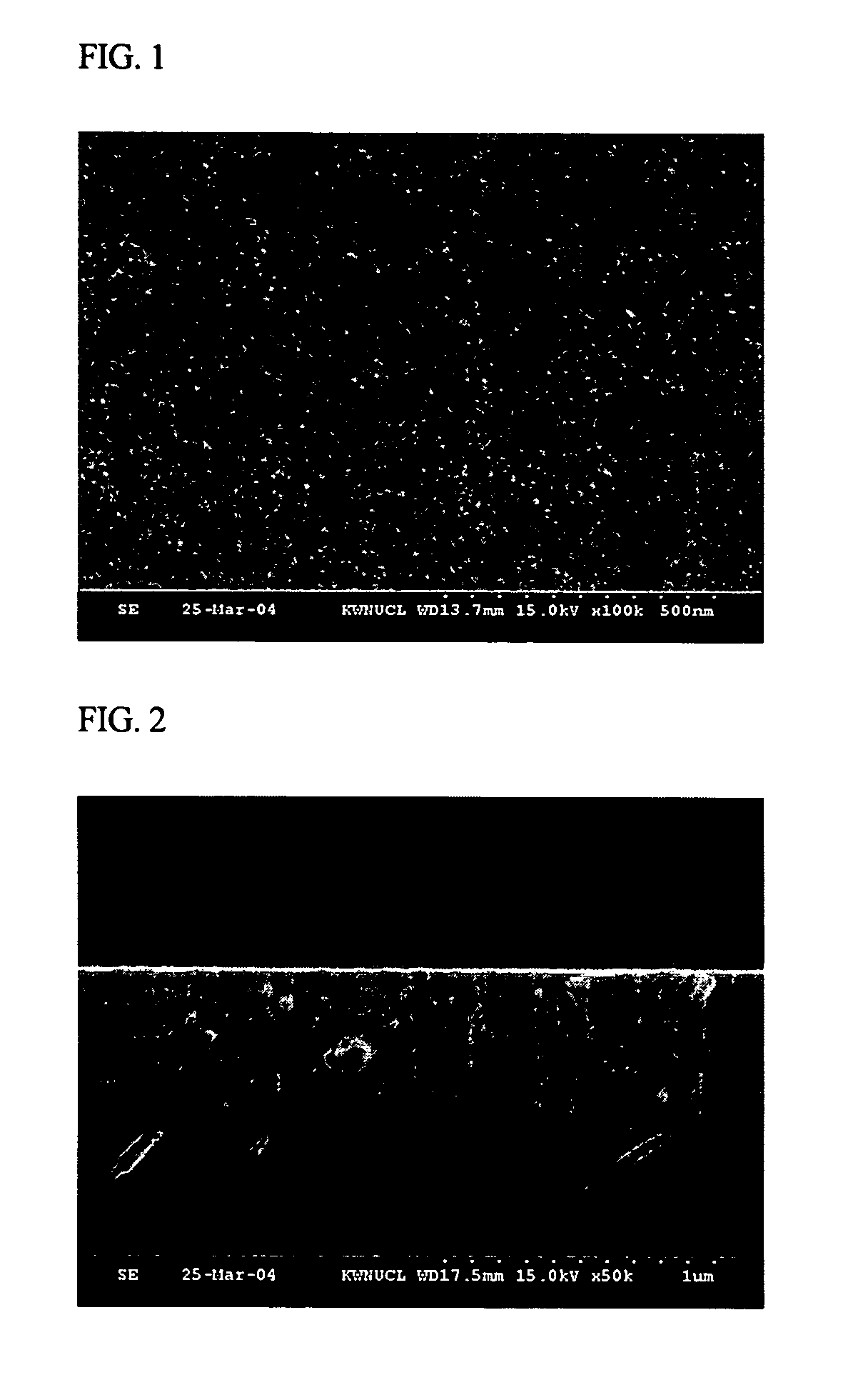
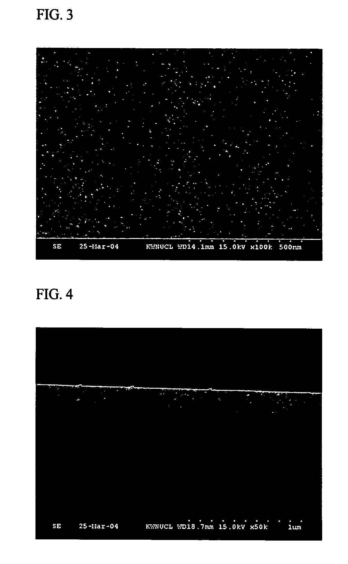
[0054]FIGS. 1 and 2 show SEMs of the surface (FIG. 1) and vertical cross-section (FIG. 2) of the Si thin film obtained in Experiment A, respectively. FIGS. 3 and 4 show SEMs of the surface (FIG. 3) and vertical cross-section (FIG. 4) of the Si thin film obtained in Experiment B, respectively.

[0055] The Si thin film in Experiment A revealed a columnar structure having rough surface morphology and cross section, while the Si thin film in Experiment B revealed a smoother vapor-deposition surface due to application of bias voltage.

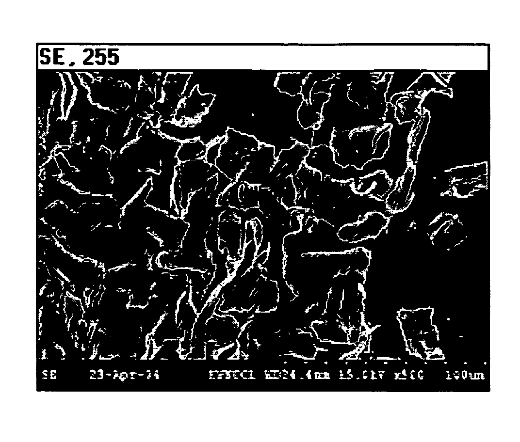
[0056] These Si thin films were subjected to charge / discharge experiments as in Example 1. FIG. 5 shows an SEM of the surface ...

example 3

[0057] Instead of a Ni foil, a Cu foil was surface-treated using the same procedure as in Example 1, and the experiment was repeated by applying DC bias voltage of −100 V using the same procedure as in Example 2.

[0058]FIG. 9 shows an SEM of the surface of the etched Cu foil, and FIG. 13 is a graph showing charge / discharge cycle characteristics of the battery fabricated using this Cu foil.


PUM

PropertyMeasurementUnit
depthaaaaaaaaaa
sizeaaaaaaaaaa
temperatureaaaaaaaaaa

Abstract

The present invention relates to a method for improving charge/discharge cycle characteristics of a lithium secondary battery using a Si based anode active material, the method comprising surface-treating a surface of an anode current collector to have specific morphology, and preferably vapor-depositing a silicon film, as the anode active material by sputtering under application of bias voltage to the surface-treated anode current collector, and/or disposing an adhesive layer between the surface-treated anode current collector and silicon film, so as to reinforce bondability between the anode current collector and active material, ultimately leading to improvement of charge/discharge characteristics of the battery.

Description

FIELD OF THE INVENTION [0001] The present invention relates to a method for improving charge / discharge cycle characteristics of a lithium secondary battery using a Si based anode active material. More specifically, the present invention relates to a method for improving charge / discharge characteristics of a lithium secondary battery by surface-treating a surface of an anode current collector to have specific morphology, and preferably vapor-depositing a silicon film, as the anode active material by sputtering under application of bias voltage to the surface-treated anode current collector, and / or disposing an adhesive layer between the surface-treated anode current collector and silicon film, so as to reinforce bondability between the anode current collector and active material, ultimately leading to improvement of charge / discharge cycle characteristics of the battery. BACKGROUND OF THE INVENTION [0002] Technological development and increased demand for mobile instruments has lead t...

Claims


Application Information

Patent Timeline
Patent Type & Authority Applications(United States)
IPC IPC(8): H01B13/00B44C1/22H01M4/64
CPCH01M4/0421H01M4/0426H01M4/134H01M4/38Y02E60/122H01M4/667H01M10/052H01M2004/027H01M4/661H01M4/386Y02E60/10H01M4/64
Inventor LEE, SUNG-MANLEE, SEO-JAE
Owner LG ENERGY SOLUTION LTD
Why Eureka
Try Eureka