Ultra sensitive in-situ magnetometer system

a technology of ultra-thin film and insitu magnetometer, which is applied in the direction of magnetic measurements, instruments, measurement devices, etc., can solve the problems of inability to monitor the magnetic moment of the thin film during the film deposition, the inability to produce measurement results, and the inability to examine the magnetic properties acquired during the process of depositing ultra-thin film. , to achieve the effect of removing the frequency shi

Inactive Publication Date: 2007-01-11
POSSIBLE ENERGY
View PDF4 Cites 6 Cited by
  • Summary
  • Abstract
  • Description
  • Claims
  • Application Information

AI Technical Summary

Benefits of technology

[0015] Therefore, the present invention has been made in view of the above and other problems, and it is one object of the present invention to provide an ultra sensitive in-situ magnetometer system that can consecutively monitor magnetic properties of thin film while carrying out a deposition process without breaking a vacuum in the chamber.
[0016] It is another object of the present invention to provide an ultra sensitive in-situ magnetometer system that can measure properties of a magnetic thin film with sub-monolayer precision while depositing the magnetic thin film.
[0017] It is yet another object of the present invention to provide an ultra sensitive in-situ magnetometer system that can examine magnetic properties of ultra thin magnetic film multi-layers necessary for conducting research on the effect of giant magneto resistance and research on the improvement of the areal memory density of magnetic recording media.

Problems solved by technology

However, the conventional system can monitor the magnetic moments of thin films only after the thin film has been deposited, such that there is a problem in that it cannot monitor the magnetic moment of the thin film during the film deposition.
Furthermore, the conventional monitoring system must perform measurement after the thin film has been deposited and a vacuum has been broken, such that there is a problem in that the thin film is oxidized and a measurement result can be produced only after the thin film has been deposited.
Part of the conventional monitoring system can perform measurement without breaking the vacuum state, but there is still a problem in that a measurement result can be produced only after the thin film has been deposited.
Furthermore, the conventional monitoring system can measure properties of a magnetic film with several Angstrom precision, but cannot measure properties of a magnetic film with sub-angstrom precision, such that there is a drawback in that magnetic properties acquired from a process for depositing a ultra-thin film cannot be examined.

Method used


Image

  • Ultra sensitive in-situ magnetometer system
  • Ultra sensitive in-situ magnetometer system
  • Ultra sensitive in-situ magnetometer system

Examples


embodiment 1

[0031] Now, an ultra sensitive in-situ magnetometer system in accordance with the present invention will be described.

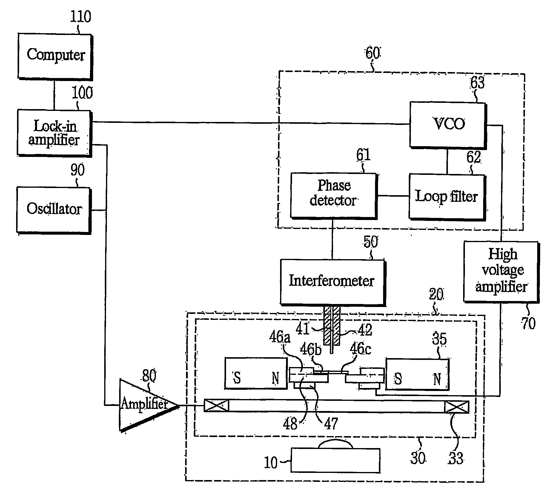
[0032] As shown in FIG. 1, the system in accordance with the present invention comprises a deposition source 10, a deposition head 30, an interferometer 50, a phase locked loop (PLL) 60, a high voltage amplifier 70, a power amplifier 80, an oscillator 90, a lock-in amplifier 100 and a computer 110. The PLL 60 consists of three parts of a phase detector 61, a loop filter 62, and a voltage controlled oscillator (VCO) 63.

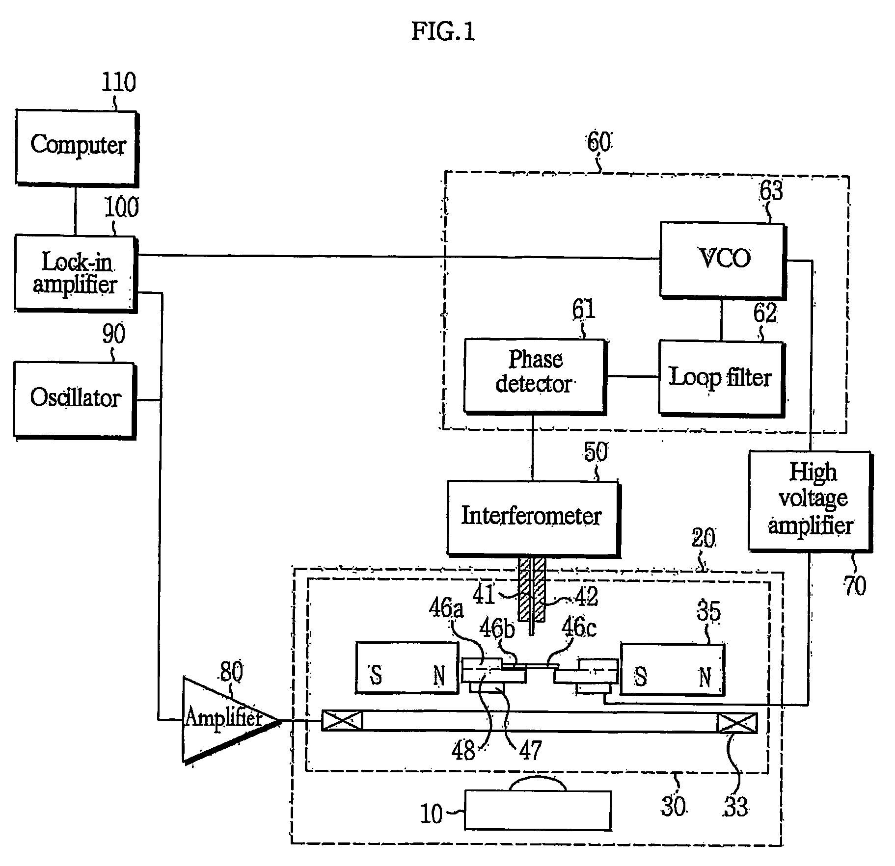
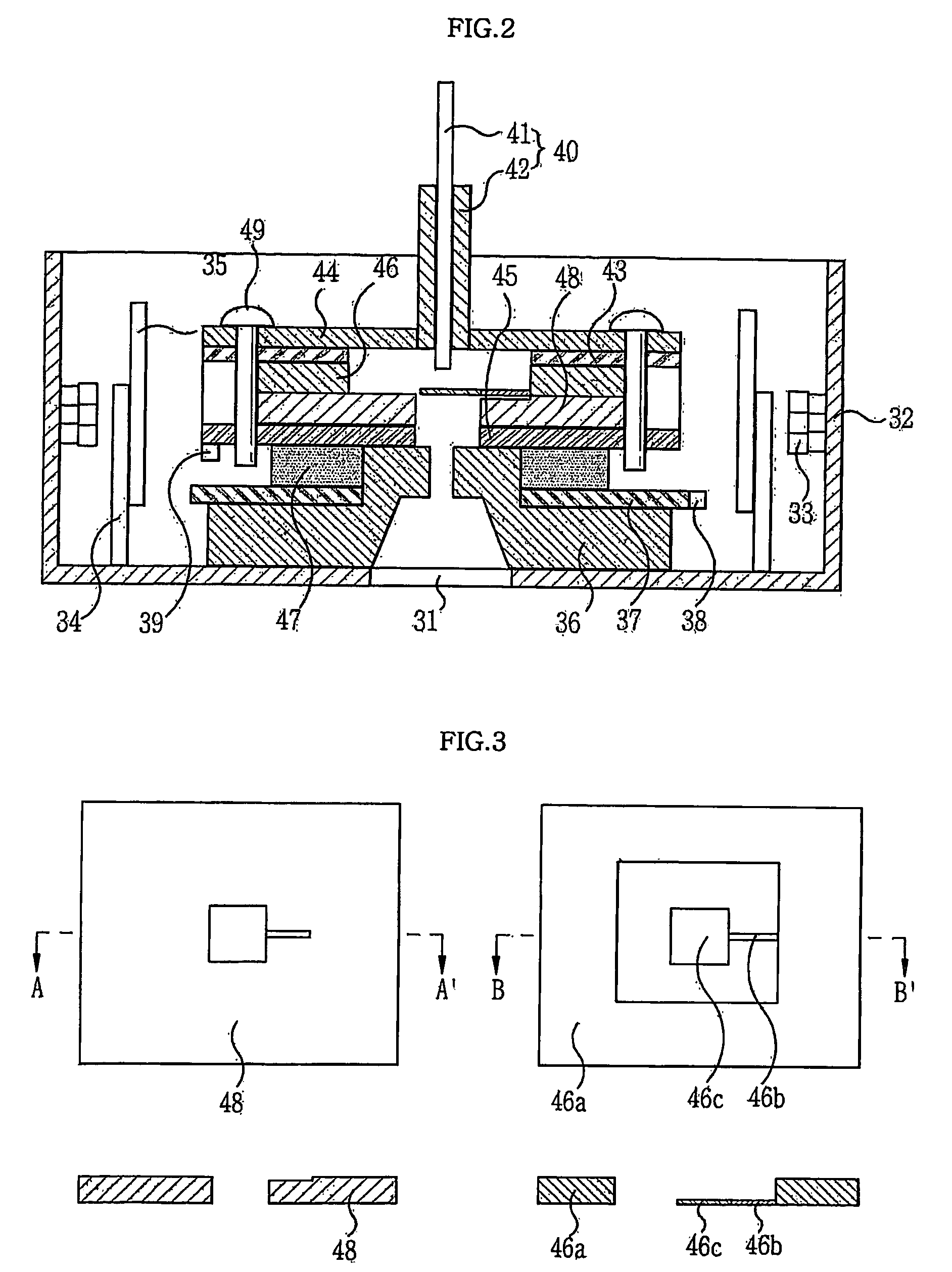
[0033] First, the deposition source 10 and the deposition head 30 are installed inside an ultra high vacuum (UHV) chamber 20. The deposition source 10 plays a role in supplying magnetic atoms to the lower surface of cantilever paddle 46c of a cantilever chip 46 within the deposition head 30. The deposition head 30 maintains an appropriate distance between the cleaved fiber 40 of the interferometer 50 and a surface of the cantilever paddle of the chip ...

embodiment 2

[0083]FIGS. 8 and 9 show another embodiment of the ultra sensitive in-situ magnetometer system in accordance with the present invention. The ultra sensitive in-situ magnetometer system comprises: a deposition source 10; a cantilever chip in which a standard NiFe film 51 is deposited on one surface of a cantilever paddle corresponding to an optical fiber avoid using piezo material and magnetic atoms incident from the deposition source 10 are deposited on the other surface of the cantilever paddle; an interferometer 50 for outputting an electrical signal by sensing vibration of the cantilever paddle 46c; and the cantilever chip as explained in the previous invention. The ultra sensitive in-situ magnetometer system further comprises: a deposition head 30 for maintaining an appropriate distance between the cleaved fiber end of the interferometer 50 and the surface of the cantilever paddle 46c; a power amplifier 80a for rectifying voltage input from a phase locked loop (PLL) 60 and varyi...


PUM

PropertyMeasurementUnit
distanceaaaaaaaaaa
diameteraaaaaaaaaa
diameteraaaaaaaaaa

Abstract

The present invention relates to an ultra sensitive in-situ magnetometer system, and more particularly to an ultra sensitive in-situ magnetometer system that can in-situ monitor a magnetic moment of a magnetic thin film with sub-monolayer precision while depositing and growing the magnetic thin film in an ultra high vacuum (UHV) chamber.

Description

TECHNICAL FIELD [0001] The present invention relates to an ultra sensitive in-situ magnetometer system, and more particularly to an ultra sensitive in-situ magnetometer system that can in-situ monitor a magnetic moment of a magnetic thin film with sub-monolayer precision or more while depositing and growing the magnetic thin film in an ultra high vacuum (UHV) chamber. BACKGROUND [0002] Conventionally, a magnetic sensor for monitoring the magnetic moment of a magnetic thin film can be implemented using the Hall effect, the magnetoresistance effect, an induction coil, a superconducting quantum interference device (SQUID), etc. A method for measuring a magnetic field using the magnetic sensor is used as the monitoring method. [0003] First, a method using the Hall effect uses a phenomenon in which electromotive force is generated as an electric field is generated in a direction perpendicular to an electric current direction and a magnetic field direction when the magnetic field is appli...

Claims


Application Information

Patent Timeline
Patent Type & Authority Applications(United States)
IPC IPC(8): G01R33/00G01R33/12
CPCG01R33/1223
Inventor MIN, DONG-HOON
Owner POSSIBLE ENERGY
Why Eureka
Try Eureka